Toyota Sienna Service Manual: Voice Recognition Difficulty
INSPECTION PROCEDURE
1 CHECK CONDITION
- Check if the system's voice recognition level is low by using only one particular voice.
OK: System's voice recognition level is low with any voice.
2 CHECK MAP DISC
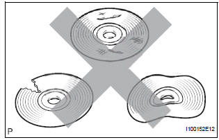
- Check that the map disc is not deformed or cracked.
OK: No deformations or cracks on map disc.
3 CHECK MAP DISC
- Check for dirt on the map disc surface.
OK: No dirt is on map disc surface.
NOTICE: Do not use a conventional record cleaner or antistatic preservative.
HINT: If the disc is dirty, clean the disc by wiping the disc's surface radially with a soft cloth.
4 CHECK MICROPHONE (NAVIGATION CHECK MODE)
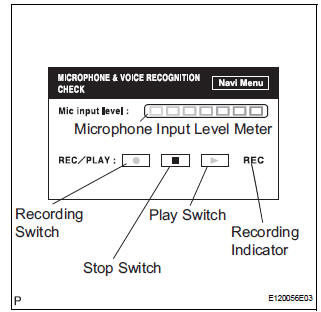
- Enter the "MICROPHONE & VOICE RECOGNITION CHECK" mode.
- When voice is input into the microphone, check that the microphone input level meter changes according to the input voice.
- Push the recording switch and perform voice recording.
HINT: Voice can be recorded up to 5 seconds.
- Check that the recording indicator remains on while recording and that the recorded voice is played normally without noise or distortion.
OK: All check results are normal.
END
 Route cannot be Calculated
INSPECTION PROCEDURE
1 CHECK MAP DISC
Check that the map disc is not deformed or cracked.
OK:
No deformations or cracks on map disc.
2 SET DESTINATION
Set another destination and che ...
 Voice is not Recognized
INSPECTION PROCEDURE
1 CHECK NAVIGATION SETTINGS
Enter the "Menu" screen by pressing the "MENU" switch.
Select "Setup
Check that "Voice Recogni ...
Other materials:
Actuator check
1. ACTUATOR CHECK
(a) After entering the DTC check mode (Sensor Check
Mode), press the R/F switch.
(b) As each damper, motor and relay automatically
operate actuator check at 1-second intervals from
step No. 1 to No. 10 continuously, check the
temperature and air flow visually and by hand. ...
Rear Air Conditioning Control Panel Circuit
DESCRIPTION
This is the rear A/C system control signal circuit as well as the power
supply circuit of the rear A/C control
assembly.
Pulse signals regarding rear A/C control panel switch operation are transmitted
between the A/C amplifier
and rear A/C control assembly.
WIRING DIAGRAM
...
Terminals of ECU
1. TELEVISION CAMERA ASSEMBLY
Disconnect the T10 camera connector
Measure the voltage and resistance of each
terminal of the wire harness side connector.
If the result is not as specified, there may be a
malfunction on the wire harness side.
Reconnect the T10 ...
