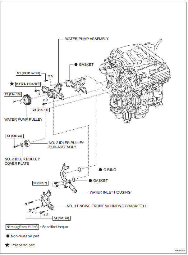
Toyota Sienna Service Manual: Water pump
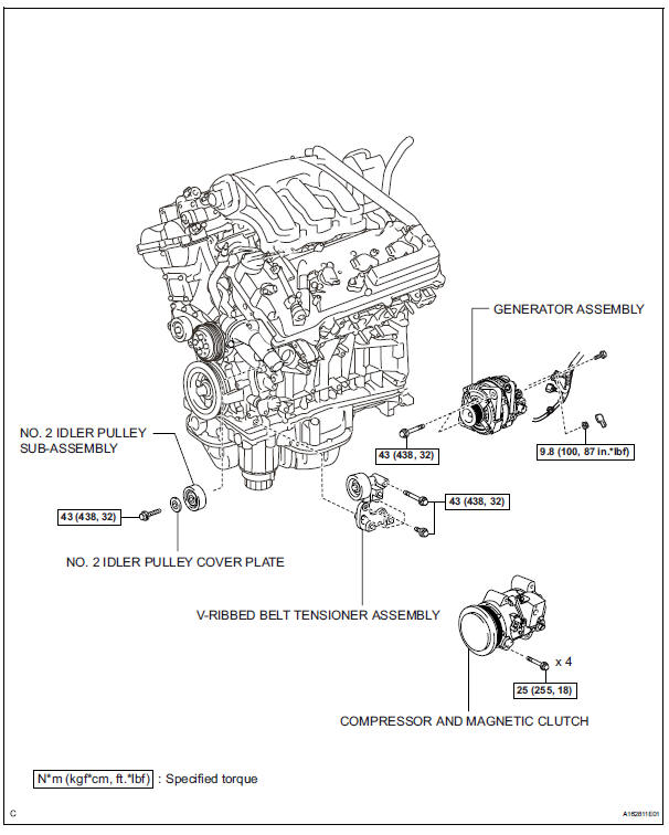
COMPONENTS
 Coolant
Replacement
1. REMOVE NO. 1 ENGINE UNDER COVER (See page
EM-26)
2. REMOVE V-BANK COVER SUB-ASSEMBLY (See
page EM-28)
3. DRAIN ENGINE COOLANT
(a) Loosen the radiator drain cock plug.
HINT:
...
 Removal
1. REMOVE ENGINE ASSEMBLY WITH TRANSAXLE
HINT:
See page EM-26
2. SECURE ENGINE (See page EM-37)
3. REMOVE GENERATOR ASSEMBLY (See page CH-17)
4. REMOVE COMPRESSOR AND MAGNETIC CLUTCH
(See page A ...
Other materials:
TC and CG Terminal Circuit
DESCRIPTION
Connecting terminals TC and CG of the DLC3 causes the system to enter the
self-diagnostic mode. If a
malfunction is present, DTCs will be output.
HINT:
When a particular warning light remains blinking, a ground short in the wiring
of terminal TC of the DLC3
or an internal grou ...
Check and replace ecu
NOTICE: • The connector should not be disconnected from
the ECU. Perform the inspection from the
backside of the connector on the wire harness
side.
• When no measuring condition is specified,
perform the inspection with the engine stopped
and the ignition switch on.
• Che ...
Disassembly
1. REMOVE NO. 1ULTRASONIC SENSOR RETAINER
(w/ Clearance Sonar System) (See page PM-19)
2. REMOVE NO. 1 ULTRASONIC SENSOR (w/
Clearance Sonar System) (See page PM-19)
3. REMOVE REAR BUMPER ENERGY ABSORBER
4. REMOVE REAR BUMPER BAR PLATE
Remove the 4 clips and the rear bumper bar plate.
5. ...
