
Toyota Sienna Service Manual: Yaw rate and deceleration sensor
Components
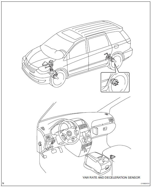
 Installation
HINT:
Install the RH side by same procedure as the LH side.
1. INSTALL REAR SPEED SENSOR
(a) Install the speed sensor rear LH with the bolt.
Torque: 8.0 N*m (82 kgf*cm, 71 in.*lbf)
NOTICE:
K ...
 Removal
HINT:
Don't use the dropped or damaged yawrate sensor
Free from the foreign matters between yaerate sensor
bracket and body.
Make sure the sensor direction.
1. REMOVE FRONT SEAT ASSEMBLY ...
Other materials:
Television Display Assembly Communication Error
INSPECTION PROCEDURE
1 IDENTIFY THE COMPONENT SHOWN BY THE SUB-CODE
Enter the diagnostic mode.
Press the preset switch "3" to change to "Detailed
Information Mode".
Identify the component shown by the sub-code.
HINT:
"190 (radio receiver)" ...
Problem symptoms table
HINT:
Use the table below to help determine the cause of the
problem symptom. The potential causes of the symptoms
are listed in order of probability in the "Suspected Area"
column of the table. Check each symptom by checking the
suspected areas in the order they are listed. Re ...
Stowing the third seats (manual seats)
Before stowing or returning third seat, remove any items from the floor
area to prevent interference with moving parts.
Before stowing the third seats
Lower the center head
restraint to the lowest position
, and stow the
seat belt buckles.
Stow the center seat belt.
Stowing ...
