Toyota Sienna Service Manual: Yaw rate sensor check (when using intelligent tester)
(a) Check the output of the yaw rate sensor.
(1) Move the shift lever to the D position, drive the vehicle at a speed of approximately 5 km/h (3 mph), and turn the steering wheel either to the left or right 90° or more until the vehicle makes a 180° turn.
(2) Stop the vehicle and move the shift lever to the P position. Check that the skid control buzzer sounds for 3 seconds.
HINT:
- If the skid control buzzer sounds, the signal check is completed normally.
- If the skid control buzzer does not sound, check the skid control buzzer circuit, then perform the signal check again.
- If the skid control buzzer does not sound yet, there is a malfunction in the VSC sensor, so check the DTC.
- Make 180° turn. At the end of the turn, the direction of the vehicle should be within 180° +- 5° of its start position.
- Do not spin the wheels.
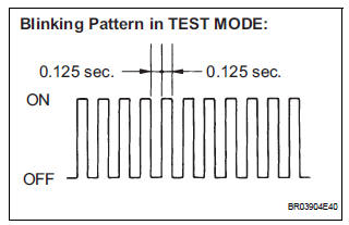
6. DTC OF TEST MODE (SIGNAL CHECK) FUNCTION
ABS sensor: 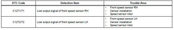
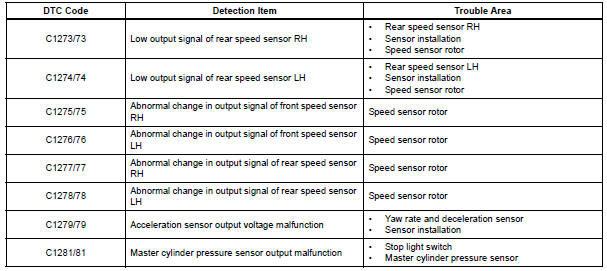
VSC sensor:
HINT: The codes in this table are output only in Test Mode (signal check).
 Speed sensor check (when using intelligent tester)
(a) Check the backward signal.
(1) Drive the vehicle in reverse for more than 1
second at 3 km/h (2 mph) or higher.
HINT:
Drive the vehicle in reverse and check the speed
sensor signal. Note th ...
 Sensor signal check by test mode (signal check) (when using sst check wire)
(a) When having replaced the skid control ECU and/or
yaw rate and deceleration sensor, perform zero
point calibration of the yaw rate and deceleration
sensor.
HINT:
If the ignition switch is t ...
Other materials:
Center Airbag Sensor Assembly Malfunction
DTC B1100/31 Center Airbag Sensor Assembly Malfunction
DESCRIPTION
The center airbag sensor assembly consists of the center airbag sensor
assembly, safing sensor, drive
circuit, diagnosis circuit and ignition control, etc.
It receives signals from the airbag sensor, judges whether or not the ...
Front floor footrest
COMPONENTS
Removal
1. REMOVE FRONT FLOOR FOOTREST
Using a screwdriver, disengage the 2 clips and
remove the footrest.
HINT:
Tape the screwdriver tip before use.
Disengage the clips and then remove the 2 clips
from the footrest.
INSTALLATION
1. INSTALL FRONT FLOOR FOOTREST ...
Cannot Call in a Certain Place
INSPECTION PROCEDURE
1 CHECK SURROUNDING CONDITIONS
Check if the cellular phone can make calls in a certain
place.
OK:
It can make calls
2 CHECK RECEPTION
Enter the "Information" screen by pressing the "INFO"
switch.
Select "Telephone".
...
