Toyota Sienna Service Manual: Yaw rate sensor check (when using sst check wire)
(a) Check the zero point voltage of the yaw rate sensor.
(1) Keep the vehicle in a stationary condition on a level surface for 1 second or more.
(b) Check the output of the yaw rate sensor.
(1) Move the shift lever to the D position, drive the vehicle at a speed of approximately 3 mph (5 km/h), and turn the steering wheel either to the left or right 90° or more until the vehicle makes 180° turn.
(2) Stop the vehicle and move the shift lever to the position. Check that the skid control buzzer sounds for 3 seconds.
HINT:
- If the skid control buzzer sounds, the signal check is completed normally.
- If the skid control buzzer does not sound, check the skid control buzzer circuit, then perform the signal check again.
- If the skid control buzzer does not sound yet, there is a malfunction in the yaw rate sensor, so check the DTC.
- Make a 180° turn. At the end of the turn, the direction of the vehicle should be within 180 +- 5° of its start position.
- Do not spin the wheels.
11. DTC OF TEST MODE (SIGNAL CHECK) FUNCTION
ABS sensor: 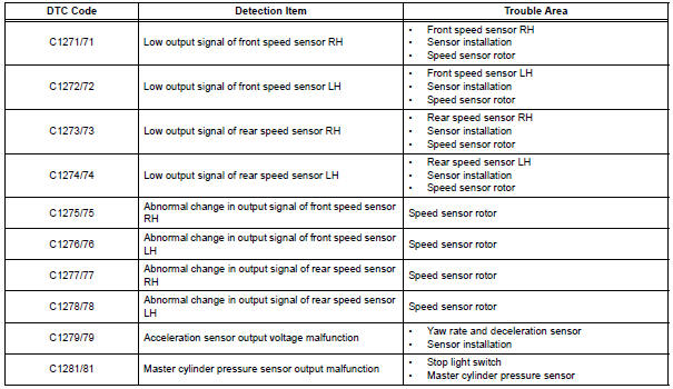
VSC sensor: 
HINT: The codes in this table are output only in Test Mode (signal check).
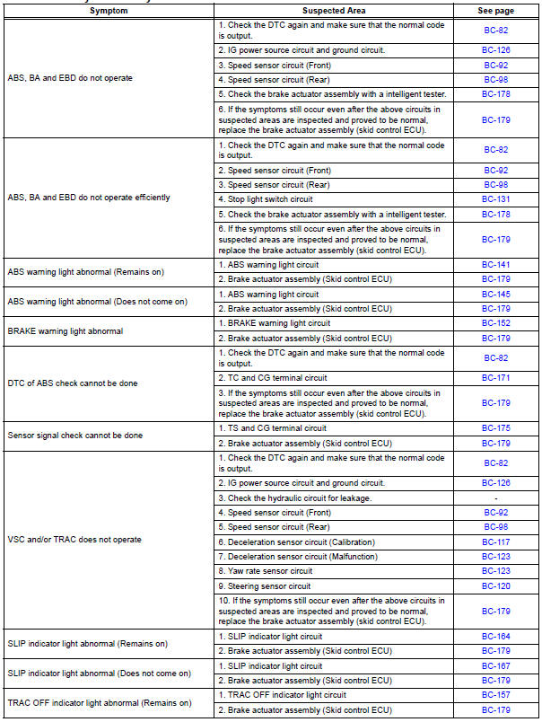
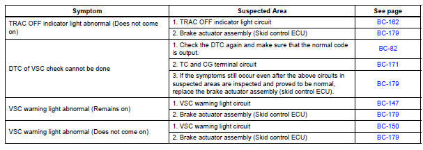
Problem symptoms table
Vehicle Stability Control System:
 Speed sensor check (when using sst check wire)
(a) Check the speed sensor signal.
(1) Drive the vehicle straight forward. Drive the
vehicle at a speed of 45 km/h (28 mph) or higher
for several seconds and check that the ABS
warning light goe ...
 Terminals of ecu
1. Terminal of ECU
(*1): Models with dynamic laser cruise control
(*2): 2WD model
2. Terminal Inspection
(a) Disconnect the connector and measure the voltage
or resistance on the wire harness ...
Other materials:
Ignition Coil "A" Primary
HINT:
These DTCs indicate malfunctions relating to the primary circuit.
If DTC P0351 is set, check the No. 1 ignition coil with igniter circuit.
If DTC P0352 is set, check the No. 2 ignition coil with igniter circuit.
If DTC P0353 is set, check the No. 3 ignition coil with igniter circ ...
Slide Door Closer LH does not Operate
DESCRIPTION
The slide door ECU LH controls the slide door closer. In response to the
output signals from the switches
in the slide door lock, the slide door closer drives the closer motor.
HINT:
The slide door closer system operates regardless of the power slide door main
switch ON / OFF.
W ...
On-vehicle inspection
1. INSPECT REAR AIRBAG SENSOR (VEHICLE NOT
INVOLVED IN COLLISION)
Perform a diagnostic system check.
2. INSPECT REAR AIRBAG SENSOR (VEHICLE
INVOLVED IN COLLISION AND AIRBAG HAS NOT
DEPLOYED)
Perform a diagnostic system check.
When the quarter panel of the vehicle or ...
