Toyota Sienna Service Manual: Back Sonar Sensor LH Circuit
DESCRIPTION
An ultrasonic sensor consists of a sensor portion that transmits and receives ultrasonic waves and a preamplifier that amplifies them. The ultrasonic sensor outputs the ultrasonic waves and sends the received signals to the clearance warning ECU.
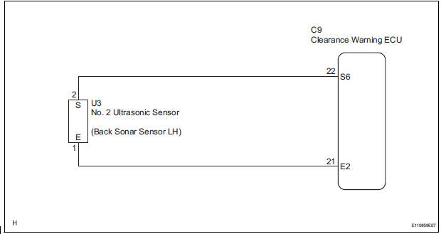
WIRING DIAGRAM
INSPECTION PROCEDURE
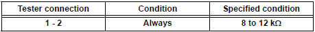
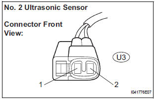
1 INSPECT NO. 2 ULTRASONIC SENSOR
- Remove the No. 2 ultrasonic sensor.
- Measure the resistance according to the value(s) in the table below.
Standard resistance
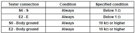
2 CHECK HARNESS AND CONNECTOR (CLEARANCE WARNING ECU - NO. 2 ULTRASONIC SENSOR)
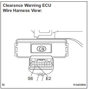
- Disconnect the C9 connector from the clearance warning ECU.
- Disconnect the U3 connector from the No. 2 ultrasonic sensor.
- Measure the resistance according to the value(s) in the table below.
Standard resistance
PROCEED TO NEXT CIRCUIT INSPECTION SHOWN IN PROBLEM SYMPTOMS TABLE
 Speed Signal Circuit
DESCRIPTION
The clearance warning ECU receives the vehicle speed signal from the
combination meter.
HINT:
A voltage of 12 V or 5 V is output from each ECU and then input to
the combin ...
 Back Sonar Sensor RH Circuit
DESCRIPTION
An ultrasonic sensor consists of a sensor portion that transmits and receives
ultrasonic waves and a preamplifier
that amplifies them. The ultrasonic sensor outputs the ultrasonic wave ...
Other materials:
Abbreviations used in manual
...
Clock
PARTS LOCATION
On-vehicle inspection
1. INSPECT INTEGRATION CONTROL & PANEL ASSEMBLY
Disconnect the A9 connector.
Measure the voltage according to the value(s) in the
table below.
Standard voltage
Measure the resistance according to the value(s) in
the ...
Air conditioning filter
The air conditioning filter must be changed regularly to maintain
air conditioning efficiency
Removal method
Turn the engine switch to the “LOCK” position (vehicles without a
smart key system) or off (vehicles with a smart key system).
Open the glove box. Slide off
the damper.
...
