Toyota Sienna 2010-2024 Owners Manual: Changing shift ranges in S mode
To enter S mode, shift the shift lever to S. Shift ranges can be selected by operating the shift lever, allowing you to drive in the shift range of your choosing. The shift range can be selected by the shift lever.
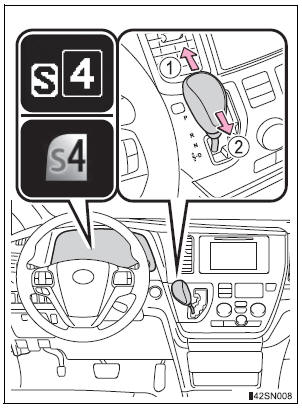
- Upshifting
- Downshifting
The selected shift range, from 1 to 6, will be displayed on the multiinformation display.
The initial shift range in S mode is set automatically to 5 or 4 according to vehicle speed. However, the initial shift range may be set to 3 if the AI-SHIFT has operated while the shift lever was in the D position.
Shift ranges and their functions
- Automatically selecting gears between 1 and 6 according to vehicle speed and driving conditions. But, the gear is limited according to selected shift range.
- You can choose from 6 levels of engine braking force.
- A lower shift range will provide greater engine braking force than a higher shift range, and the engine speed will also increase.
S mode
- When the shift range is 5 or lower, holding the shift lever toward “+” sets the shift range to 6.
- To prevent excessive engine speed, a function was adopted that automatically selects a higher shift range before the engine speed becomes too high.
- To protect the automatic transaxle, a function is adopted that automatically selects a higher shift range when the fluid temperature is high.
Downshift restriction warning buzzer (S mode)
To help ensure safety and driving performance, downshifting operation may sometimes be restricted. In some circumstances, downshifting may not be possible even when the shift lever is operated. (A buzzer will sound twice.)
When driving with the cruise control or dynamic radar cruise control activated (if equipped)
Even when performing the following actions with the intent of enabling engine braking, engine braking will not activate while driving in S mode and downshifting to 5 or 4 because cruise control or dynamic radar cruise control will not be canceled. (, 263)
If the shift lever cannot be shifted from P
- Vehicles with AUTO ACCESS SEAT: If the AUTO ACCESS SEAT has not
been locked in place after being stowed, the shift lever cannot be shifted
from P.
For details, refer to “AUTO ACCESS SEAT OWNER’S MANUAL”.
If “S” does not come on even after shifting the shift lever to S
This may indicate a malfunction in the automatic transaxle system. Have the vehicle inspected by your Toyota dealer immediately. (In this situation, the transaxle will operate in the same manner as when the shift lever is in D.)
AI-SHIFT
AI-SHIFT automatically selects the suitable gear according to driver performance and driving conditions.
AI-SHIFT automatically operates when the shift lever is in the D position.
(Shifting the shift lever to the S position cancels the function.)
| WARNING When driving on slippery road surfaces Do not accelerate or shift gears suddenly. Sudden changes in engine braking may cause the vehicle to spin or skid, resulting in an accident. |
 Shift position purpose
*1: Shifting to the D position allows the system to select a gear suitable
for
the driving conditions. Setting the shift lever to the D position is recommended
for normal driving.
*2: Selec ...
 Turn signal lever
Operating instructions
Right turn
Left turn
Lane change to the right (move
the lever partway and release
it)
The right hand signals will flash 3
times.
Lane change to the left (m ...
Other materials:
Installation
1. INSTALL YAW RATE AND DECELERATION SENSOR
(a) Connect the yawrate sensor connector.
(b) Install the yawrate sensor with the 2 bolts.
Torque: 13 N*m (136 kgf*cm, 10 ft.*lbf)
2. INSTALL COWL SIDE TRIM BOARD RH
(a) Install the nut with the cowl side trim board plate
RH.
3. INSTALL FRONT ...
CAN Bus Line
DESCRIPTION
When any DTC for the CAN communication system is output, first measure the
resistance between the
terminals of the DLC3 to specify the trouble area, and check that there is no
short in the CAN main wire,
between the main wire, and +B or GND.
WIRING DIAGRAM
INSPECTION PRO ...
Bulb locations
Front
Vehicles without daytime running lights or with bulb type daytime
running lights
Headlight high beam and daytime
running lights (if equipped)
Headlight low beam
(halogen bulb)
Fog light (if equipped)
Front turn signal/parking and
front side marker lights
Vehic ...
