Toyota Sienna Service Manual: Crankshaft position sensor
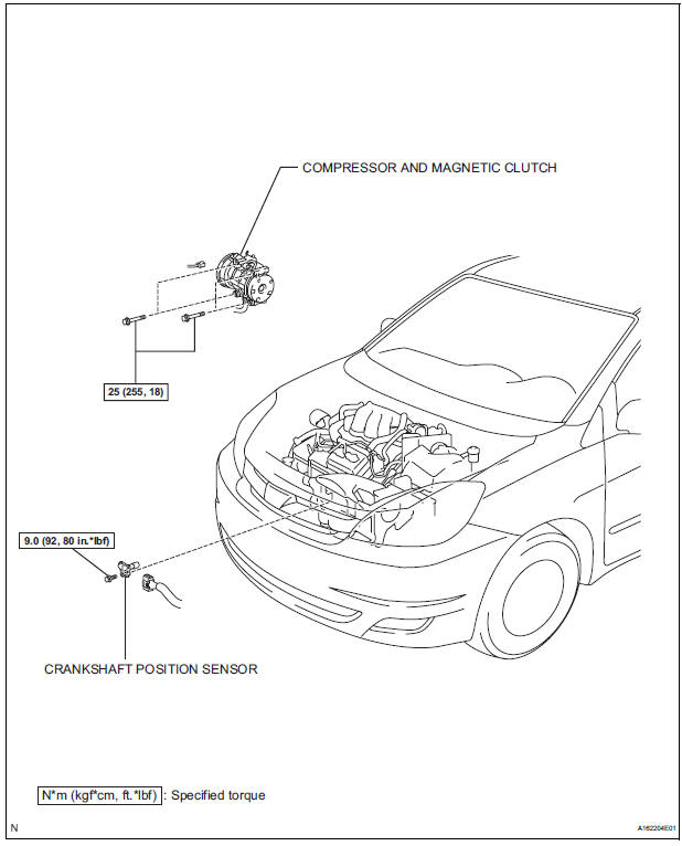
Components
Removal
1. Remove compressor and magnetic clutch
HINT: (See page AC-227 )
2. REMOVE CRANKSHAFT POSITION SENSOR
(a) Disconnect the crankshaft position sensor connector.
(b) Remove the bolt, and then remove the crankshaft position sensor.
INSPECTION
1. INSPECT CRANKSHAFT POSITION SENSOR
(a) Using an ohmmeter, measure the resistance between the terminals.
Standard resistance 
NOTICE:
|
If the resistance is not as specified, replace the crankshaft position sensor.
INSTALLATION
1. INSTALL CRANKSHAFT POSITION SENSOR
(a) Apply a light coat of engine oil to the O-ring on the crankshaft position sensor.
(b) Install the crankshaft position sensor with the bolt.
Torque: 9.0 N*m (92 kgf*cm, 80 in.*lbf) (c) Connect the crankshaft position sensor connector.
2. INSTALL COMPRESSOR AND MAGNETIC CLUTCH
HINT: (See page AC-231)
 Vvt sensor
COMPONENTS
ON-VEHICLE INSPECTION
1. CHECK VVT SENSOR OUTPUT VOLTAGE
(a) Turn the ignition switch to the ON position.
(b) Check the voltage between the specified terminal
and body grou ...
 Engine coolant temperature sensor
COMPONENTS
REMOVAL
1. DRAIN ENGINE COOLANT (See page CO-6)
2. REMOVE V-BANK COVER SUB-ASSEMBLY (See
page EM-28)
3. REMOVE NO. 2 AIR CLEANER INLET (See page EM-
28)
4. REMOVE NO. 1 AIR CLEAN ...
Other materials:
Power window regulator
motor
INSPECTION
1. INSPECT POWER WINDOW REGULATOR MOTOR
(FRONT RH)
Remove the power window regulator motor.
Apply battery voltage to the motor connector
according to the table below.
NOTICE:
Do not apply battery to any terminals except
terminals 1 and 2.
Standard
2. INS ...
Installation
1. INSTALL TIRE PRESSURE WARNING VALVE AND TRANSMITTER
(a) Insert the tire pressure warning valve and
transmitter into the valve installation hole. Insert it
from the inside of the rim so that the printed surface
can be seen.
NOTICE:
Check that there is no visible deformation,
damage, ...
Operating the audio system
Press this button to eject a disc
Insert a disc into the disc slot
Press to pause or resume playing music.
Press the ‚Äú<‚ÄĚ or ‚Äú>‚ÄĚ button to seek up or down for a radio station, or
to access a desired track or file.
Turn this knob to select radio station bands, tracks and ...
