Toyota Sienna Service Manual: Engine coolant temperature sensor
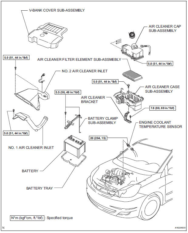
COMPONENTS
REMOVAL
1. DRAIN ENGINE COOLANT (See page CO-6) 2. REMOVE V-BANK COVER SUB-ASSEMBLY (See page EM-28) 3. REMOVE NO. 2 AIR CLEANER INLET (See page EM- 28) 4. REMOVE NO. 1 AIR CLEANER INLET (See page EM- 28) 5. REMOVE AIR CLEANER CAP SUB-ASSEMBLY (See page ES-493) 6. REMOVE AIR CLEANER CASE SUB-ASSEMBLY (See page EM-28) 7. REMOVE ENGINE COOLANT TEMPERATURE SENSOR
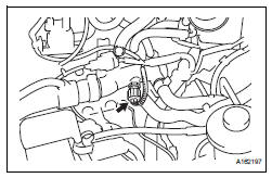
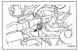
(a) Remove the engine coolant temperature sensor connector.
(b) Remove the engine coolant temperature sensor.
INSPECTION
1. INSPECT ENGINE COOLANT TEMPERATURE SENSOR
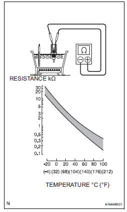
(a) Using an ohmmeter, measure the resistance between the terminals.
Standard resistance 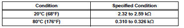
- If the result is as specified, do not replace the engine coolant temperature sensor
- If the result is not as specified, replace the engine coolant temperature sensor.
| NOTICE: In case of checking the engine coolant temperature sensor in water, do not allow water to go into the terminals. After checking, dry the engine coolant temperature sensor. |
INSTALLATION
1. INSTALL ENGINE COOLANT TEMPERATURE SENSOR
(a) Install the engine coolant temperature sensor.
Torque: 20 N*m (204 kgf*cm, 15 ft.*lbf) (b) Connect the engine coolant temperature sensor connector.
2. INSTALL AIR CLEANER CASE SUB-ASSEMBLY (See page EM-59) 3. INSTALL AIR CLEANER CAP SUB-ASSEMBLY (See page ES-496) 4. INSTALL NO. 1 AIR CLEANER INLET (See page EM- 59) 5. INSTALL NO. 2 AIR CLEANER INLET (See page EM- 60) 6. ADD ENGINE COOLANT (See page CO-7) 7. INSPECT FOR ENGINE COOLANT LEAK (See page CO-1) 8. INSTALL V-BANK COVER SUB-ASSEMBLY (See page EM-63)
 Crankshaft position sensor
Components
Removal
1. Remove compressor and magnetic clutch
HINT:
(See page AC-227 )
2. REMOVE CRANKSHAFT POSITION SENSOR
(a) Disconnect the crankshaft position sensor
connector.
(b) R ...
 Knock sensor
COMPONENTS
REMOVAL
1. DISCHARGE FUEL SYSTEM PRESSURE
(See page FU-13)
2. REMOVE V-BANK COVER SUB-ASSEMBLY (See
page EM-28)
3. DRAIN ENGINE COOLANT (See page CO-6)
4. REMOVE WINDSHIE ...
Other materials:
Half Connection in Center Airbag Sensor
Assembly Connectors
DTC B1135/24 Half Connection in Center Airbag Sensor
Assembly Connectors
DESCRIPTION
The center airbag sensor assembly connector has a mechanism that electrically
detects half connection.
The center airbag sensor assembly monitors the voltage applied to the
disconnection detection pins and ...
Random / Multiple Cylinder Misfire Detected
DESCRIPTION
When the engine misfires, high concentrations of hydrocarbons (HC) enter the
exhaust gas. High HC
concentration levels can cause increase in exhaust emission levels. Extremely
high concentrations of HC
can also cause increases in the Three-Way Catalytic Converter (TWC) tem ...
Adjustment
1. INSPECT SHIFT LEVER POSITION
(a) When shifting from P to R position only with ignition
switch ON and brake pedal, make sure that the
shifting lever moves smoothly and can be
moderately operated.
(b) When starting engine, make sure that the vehicle
moves forward when shifting from N to D p ...
