Toyota Sienna Service Manual: Data list
HINT:
Reading the DATA LIST displayed on an intelligent tester enables values, including those of the switches, sensors, and actuators, to be checked without removing any parts. Reading the DATA LIST as the first step in troubleshooting is one method to shorten diagnostic time.
| NOTICE: In the table below, the values listed under Normal Condition are for reference only. Do not depend solely on these values when determining whether or not a part is faulty. |
(a) Warm up the engine.
(b) Turn the ignition switch off.
(c) Connect an intelligent tester to the DLC3.
(d) Start the engine.
(e) Turn the tester ON.
(f) Select the following menu items: DIAGNOSIS / ENHANCED OBD II / DATA LIST.
(g) Check the values by referring to the table below.
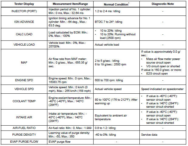
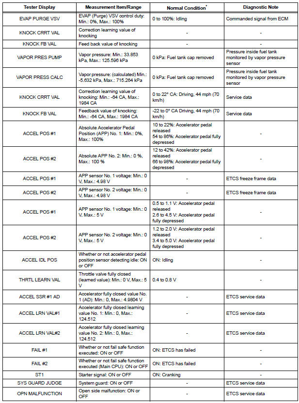
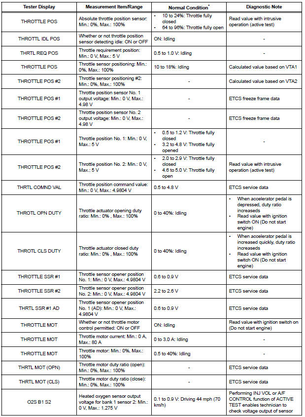
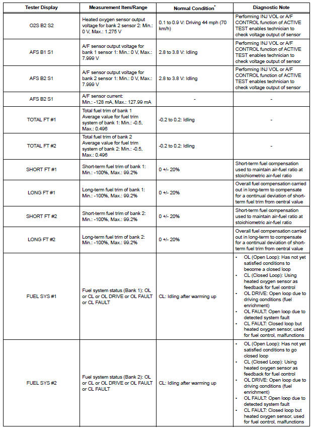
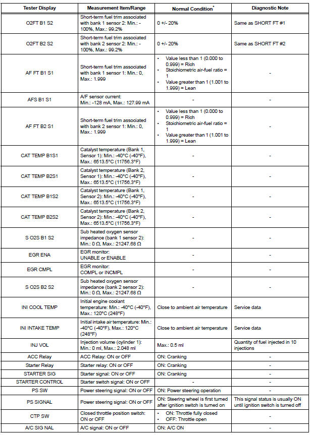
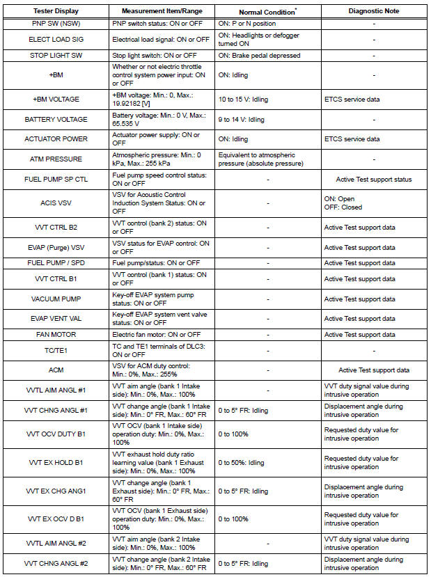
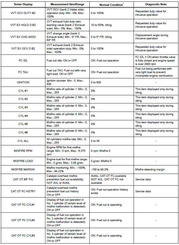
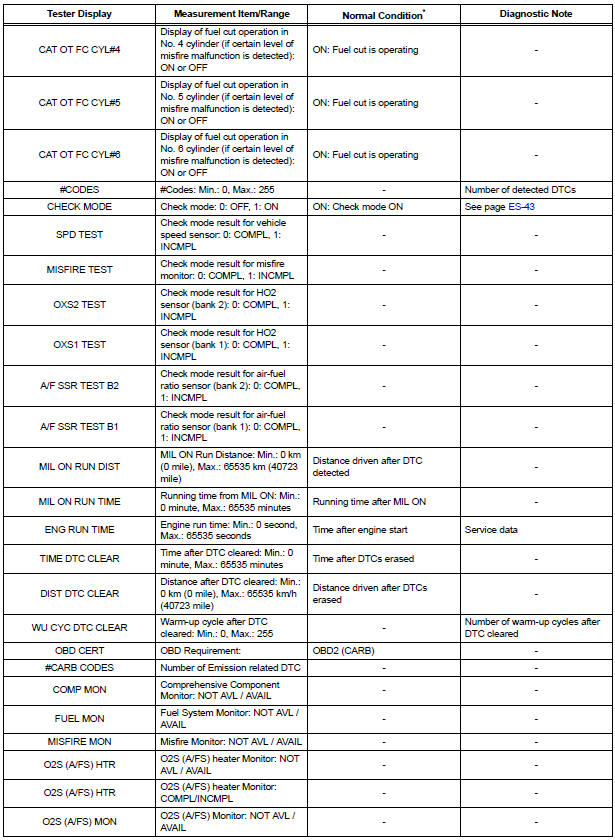
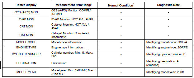
*: If no idling conditions are specified, the transmission gear selector lever should be in the N or P position, and the A/C switch and all accessory switches should be OFF.

 Active test
HINT:
Performing an ACTIVE TEST enables components
including the relays, VSV (Vacuum Switching Valve), and
actuators, to be operated without removing any parts.
The ACTIVE TEST can be performed ...
Other materials:
Headlight Relay Circuit
DESCRIPTION
The Multiplex network body ECU controls HEAD relay when signal is received
from headlight dimmer
switch assembly.
WIRING DIAGRAM
INSPECTION PROCEDURE
1 PERFORM ACTIVE TEST BY INTELLIGENT TESTER
Connect the intelligent tester to DLC3.
Turn the ignition switch ON and ...
Throttle Actuator Control Motor Current Range / Performance
DESCRIPTION
The ETCS (Electronic Throttle Control System) has a dedicated power supply
circuit. The voltage (+BM)
is monitored and when it is low (less than 4 V), the ECM determines that there
is a malfunction in the
ETCS and cuts off the current to the throttle actuator.
When the volt ...
Installation
1. INSTALL ACCELERATOR PEDAL ROD
NOTICE:
Avoid physical shock to the accelerator pedal
assembly.
Do not disassemble the accelerator pedal
assembly.
Install the accelerator pedal rod with the 2 nuts.
Torque: 4.9 N*m (50 kgf*cm, 43 in.*lbf)
Connect the ...
