Toyota Sienna Service Manual: Definition of terms
|
Terms |
Definitions |
| Monitor Description | Description of what ECM monitors and how to detect malfunctions (monitoring purpose and details). |
| Related DTCs | A group of diagnostic trouble codes that are output by ECM based on the same malfunction detection logic. |
| Typical Enabling Conditions | Preconditions that allow ECM to detect malfunction.
With all preconditions satisfied, ECM sets DTC when monitored value(s) exceeds malfunction threshold(s). |
| Sequence of Operation | Order of monitor priority, applied if multiple sensors and
components are involved in single malfunction detection
process.
Each sensor and component monitored in turn and not monitored until previous detection operation is completed |
| Required Sensors / Components | Sensors and components used by ECM to detect each malfunction |
| Frequency of Operation | Number of times ECM checks for each malfunction during each driving
cycle.
"Once per driving cycle" means ECM performs checks for that malfunction only once in single driving cycle. "Continuous" means ECM performs checks for that malfunction whenever enabling conditions are met. |
| Duration | Minimum time for which ECM must detect continuous deviation in monitored value(s) in order to set DTC. Timing begins when typical enabling conditions are met. |
| Malfunction Thresholds | Values, beyond which, ECM determines malfunctions exist and sets DTCs. |
| MIL Operation | Timing of MIL illumination after defect is detected.
"Immediate" means ECM illuminates MIL as soon as malfunction is detected. "2 driving cycles" means ECM illuminates MIL if the same malfunction is detected twice during the next sequential driving cycle. |
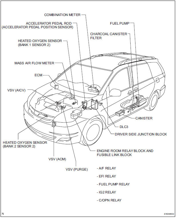
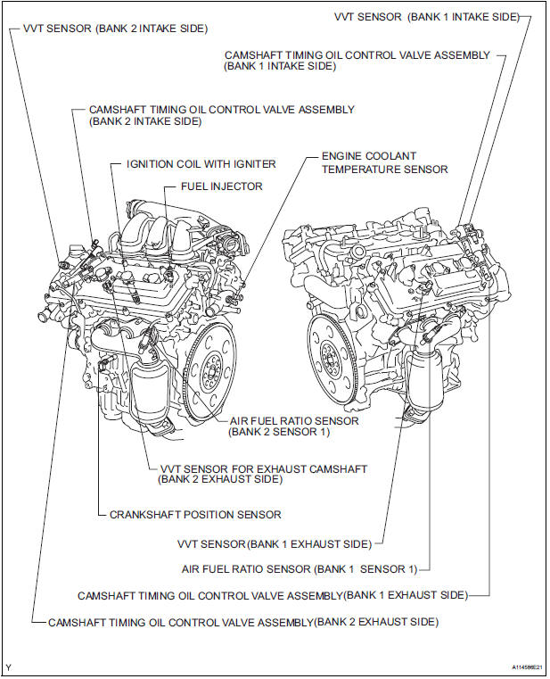
PARTS LOCATION

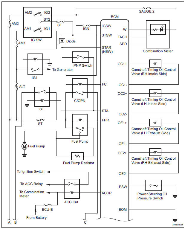
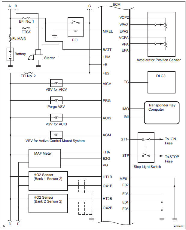
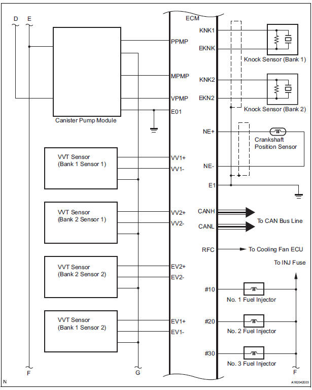
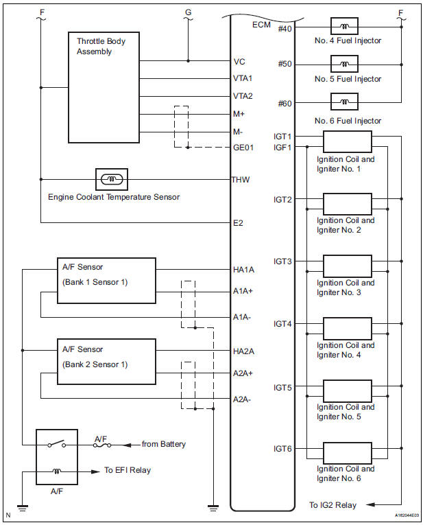
SYSTEM DIAGRAM
 Precaution
1. INITIALIZATION
NOTICE:
Perform RESET MEMORY (AT initialization) when
replacing the automatic transaxle assembly, engine
assembly or ECM.
Perform REGISTRATION (VIN registratio ...
 How to proceed with
troubleshooting
How to proceed with
troubleshooting
HINT:
The intelligent tester can be used in steps 2, 3, 4, 6 and 9.
1 VEHICLE BROUGHT TO WORKSHOP
2 CONNECT INTELLIGENT TESTER TO DLC3
HINT:
If the display indicates a communication fault in the ...
Other materials:
Air fuel ratio sensor relay
INSPECTION
1. INSPECT AIR FUEL RATIO SENSOR RELAY
Using an ohmmeter, measure the resistance
according to the value(s) in the table below.
Standard resistance
If the result is not as specified, replace the relay. ...
Short in Front Pretensioner Squib LH Circuit
DTC B0135/73 Short in Front Pretensioner Squib LH Circuit
DESCRIPTION
The front pretensioner squib LH circuit consists of the center airbag sensor
assembly and the front seat
outer belt assembly LH.
This circuit instructs the SRS to deploy when deployment conditions are met.
DTC B0135/73 ...
Current Position Display does not Appear
INSPECTION PROCEDURE
1 CHECK RADIO AND NAVIGATION ASSEMBLY
Check if a map disc is inserted into the map disc slot.
OK:
A map disc is inserted
2 CHECK MAP DISC
Check that the map disc is not deformed or cracked.
OK:
No deformations or cracks appear on the map disc.
PROCEED ...
