Toyota Sienna Service Manual: How to proceed with troubleshooting
HINT: The intelligent tester can be used in steps 2, 3, 4, 6 and 9.
1 VEHICLE BROUGHT TO WORKSHOP
2 CONNECT INTELLIGENT TESTER TO DLC3
HINT: If the display indicates a communication fault in the tester, inspect the DLC3.
3 CHECK DTC AND FREEZE FRAME DATA
- Check for DTC(s) and freeze frame data.
HINT: Record or print the DTCs and freeze frame data, if necessary.
4 CLEAR DTC AND FREEZE FRAME DATA
- Clear the DTC(s) and freeze frame data
5 CONDUCT VISUAL INSPECTION
6 SET CHECK MODE DIAGNOSIS
- Set the check mode
7 CONFIRM PROBLEM SYMPTOMS
HINT: If the engine does not start, perform steps 9 and 11 first.
Result
8 SIMULATE SYMPTOMS
9 CHECK FOR DTCS
- Check for DTCs.
Result
10 REFER TO DTC CHART
HINT: Refer to the DTC chart
GO TO STEP 13
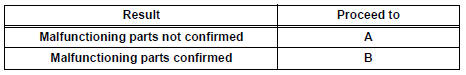
11 CONDUCT BASIC INSPECTION
HINT: Refer to "BASIC INSPECTION".
Result
12 REFER TO PROBLEM SYMPTOMS TABLE
HINT: Refer to "PROBLEM SYMPTOMS TABLE".
Result
13 CHECK ECM POWER SOURCE CIRCUIT
HINT: Refer to "ECM POWER SOURCE CIRCUIT"
14 CONDUCT CIRCUIT INSPECTION
Result
15 CHECK FOR INTERMITTENT PROBLEMS
HINT: Refer to "CHECK FOR INTERMITTENT PROBLEMS"
GO TO STEP 17
16 CONDUCT PARTS INSPECTION
17 IDENTIFY PROBLEM
18 ADJUST AND/OR REPAIR
19 CONDUCT CONFIRMATION TEST
END
 Definition of terms
Terms
Definitions
Monitor Description
Description of what ECM monitors and how to detect malfunctions
(monitoring purpose and details).
Related DTCs
A gro ...
 Check for intermittent
problems
Check for intermittent
problems
1. CHECK FOR INTERMITTENT PROBLEMS
HINT:
For use of the intelligent tester only:
Inspect the vehicle's ECM using check mode.
Intermittent problems are easier to detect with an
intelligent teste ...
Other materials:
Removal
1. REMOVE CENTER REAR SEAT LAP TYPE BELT
ASSEMBLY (for 8-Passenger)
HINT:
Refer to the instructions for disassembly of the rear No. 1
seat assembly (for center seat).
Remove the bolt and center seat lap type belt
assembly.
2. REMOVE CENTER REAR NO. 2 SEAT LAP BELT
ASSEMBLY WITH I ...
Open in Rear Curtain Shield Squib RH Circuit
DTC B1631/84 Open in Rear Curtain Shield Squib RH Circuit
DESCRIPTION
The rear curtain shield squib RH circuit consists of the center airbag sensor
assembly and the curtain
shield airbag assembly RH.
The circuit instructs the SRS to deploy when deployment conditions are met.
DTC B1631/84 ...
Short in Curtain Shield Squib LH Circuit
DTC B1165/87 Short in Curtain Shield Squib LH Circuit
DESCRIPTION
The curtain shield squib LH circuit consists of the center airbag sensor
assembly and the curtain shield
airbag assembly LH.
The circuit instructs the SRS to deploy when deployment conditions are met.
DTC B1165/87 is record ...
