Toyota Sienna Service Manual: Diagnosis Circuit
DESCRIPTION
DTC output mode is set by connecting terminals TC and CG of the DLC3.
DTCs are displayed by blinking the SRS warning light.
HINT:
- When each warning light stays blinking, a ground short in the wiring of terminal TC of the DLC3 or an internal ground short in each ECU is suspected.
- A DTC output mode signal is transmitted through BEAN and CAN to each ECU including the center airbag sensor assembly. Thus when all systems do not enter DTC output mode, there may be an ECM malfunction.
WIRING DIAGRAM
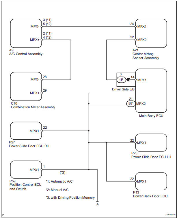
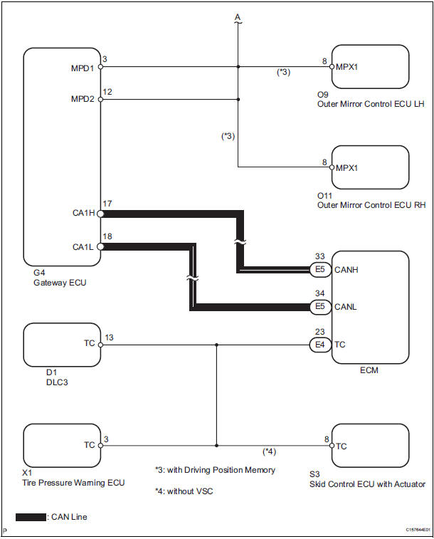
INSPECTION PROCEDURE
1 CHECK MULTIPLEX COMMUNICATION SYSTEM
- Check if the multiplex communication system DTC is output.
HINT: The center airbag sensor assembly of this system is connected to the multiplex communication system.
Therefore, before starting troubleshooting, make sure to check that there is no trouble in the multiplex communication system.
OK: The Multiplex communication system DTC is not output.
2 CHECK CAN COMMUNICATION SYSTEM
- Use the intelligent tester to check if the CAN communication system is functioning normally.
HINT: The ECM is connected to the CAN communication system. Therefore, before starting troubleshooting, make sure to check that there is no trouble in the CAN communication system.
OK: The CAN communication system is functioning normally.
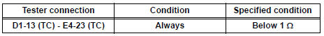
3 CHECK WIRE HARNESS (TC OF DLC3 - TC OF ECM)
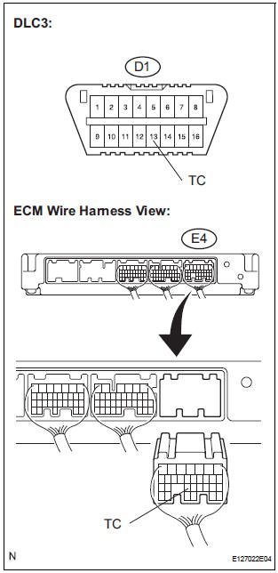
- Turn the ignition switch to the LOCK position.
- Disconnect the connector from the ECM.
- Measure the resistance according to the value(s) in the table below.
Standard resistance
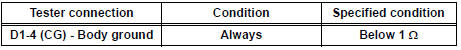
4 CHECK WIRE HARNESS (CG OF DLC3 - BODY GROUND)
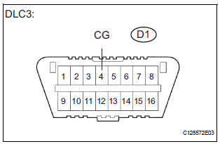
- Measure the resistance according to the value(s) in the table below.
Standard resistance
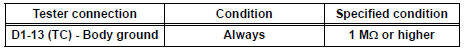
5 CHECK WIRE HARNESS (TC OF DLC3 - BODY GROUND)
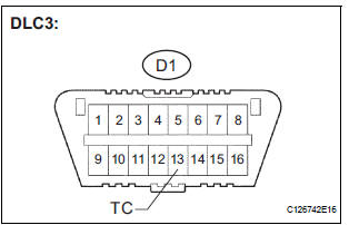
- Measure the resistance according to the value(s) in the table below.
Standard resistance
REPLACE CENTER AIRBAG SENSOR ASSEMBLY
 SRS Warning Light does not Come ON
DESCRIPTION
WIRING DIAGRAM
INSPECTION PROCEDURE
1 CHECK BATTERY
Measure the voltage of the battery.
Standard voltage:
11 to 14 V
2 CHECK CONNECTORS
Turn the ignition switch to the LOCK ...

Other materials:
The Blind Spot Monitor function detection areas
The areas that vehicles can be detected in are outlined below.
The range of the detection area
extends to:
Approximately 11.5 ft. (3.5 m)
from the side of the vehicle
The first 1.6 ft. (0.5 m) from the
side of the vehicle is not in the
detection area
Approximately 9.8 ft. (3 m) ...
Power back door drive unit
INSPECTION
1. INSPECT POWER BACK DOOR DRIVE UNIT
Remove the unit.
Apply battery voltage to the terminals and check the
motor operation.
Standard
If the result is not as specified, replace the drive
unit.
Check the resistance of the clutch terminals.
Resistance
If th ...
Intake Air Temperature Sensor Gradient Too
High
DTC P0111 Intake Air Temperature Sensor Gradient Too
High
DESCRIPTION
The Intake Air Temperature (IAT) sensor, mounted on the Mass Air Flow (MAF)
meter, monitors the IAT.
The IAT sensor has a built-in thermistor with a resistance that varies according
to the temperature of the
intake ...
