Toyota Sienna Service Manual: Disassembly
HINT: When the battery is reconnected, the back door is locked and cannot be opened. Therefore, it is necessary to unlock the back door using the door control switch or transmitter switch.
1. REMOVE BACK DOOR SCUFF PLATE (See page ET- 18)
2. REMOVE QUARTER TRIM PANEL ASSEMBLY FRONT LH
3. REMOVE RR WINDOW SIDE GARNISH ASSEMBLY NO.2 LH
4. REMOVE POWER BACK DOOR ROD
- Remove the 2 clips and rod.
5. REMOVE POWER BACK DOOR DRIVE UNIT
- Remove the 3 bolts and drive unit.
6. REMOVE BACK DOOR GARNISH CENTER
- Using a clip remover, disengage the 5 clips and remove the garnish.
7. REMOVE BACK DOOR SIDE GARNISH LH
- Using a clip remover, disengage the 3 clips and remove the side garnish.
8. REMOVE BACK DOOR SIDE GARNISH RH
- Using a clip remover, disengage the 3 clips and remove the side garnish.
9. REMOVE BACK DOOR STAY BRACKET UPPER LH
- Remove the 2 bolts and bracket.
10. REMOVE BACK DOOR PULL STRAP
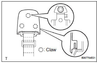
- Using a screwdriver, disengage the 3 claws and
remove the strap cover.
HINT: Tape the screwdriver tip before use.
- Remove the bolt and strap.
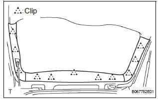
11. REMOVE BACK DOOR TRIM BOARD ASSEMBLY
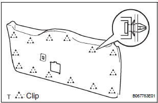
- Using a screwdriver, disengage the 14 clips and remove the trim board.
HINT: Tape the screwdriver tip before use.
12. REMOVE POWER BACK DOOR TOUCH SENSOR LH
- Remove the 4 screws.
- Using a clip remover, remove the clip and touch sensor.
13. REMOVE POWER BACK DOOR TOUCH SENSOR RH
- Remove the 4 screws.
- Using a clip remover, remove the clip and touch sensor.
14. REMOVE BACK-UP LIGHT ASSEMBLY LH (See page LI-90)
15. REMOVE BACK-UP LIGHT ASSEMBLY RH (See page LI-90)
16. REMOVE BACK DOOR GARNISH SUB-ASSEMBLY OUTSIDE
17. REMOVE BACK DOOR WITH MOTOR LOCK ASSEMBLY
- Disconnect the connector.
- Remove the 4 bolts and lock.
18. REMOVE BACK DOOR BASE STOPPER BRACKET
- Remove the 2 bolts and bracket.
19. REMOVE BACK DOOR STOPPER LOWER
- Remove the 2 bolts and stopper.
20. REMOVE REAR SPOILER COVER (See page ET-18)
21. REMOVE BACK DOOR STAY SUB-ASSEMBLY LH
22. REMOVE BACK DOOR STAY SUB-ASSEMBLY RH
 Power back door
COMPONENTS
...
 Adjustment
HINT:
On the RH side, use the same procedures as on the LH
side.
Since a centering bolt is used as door hinge mounting
bolts on the body side and the door side, the door cannot
be adjusted ...
Other materials:
Removal
HINT:
Use the same procedures for the RH side and LH side.
The procedures listed below are for the LH side.
1. PRECAUTION
CAUTION: Be sure to read "PRECAUTION" thoroughly before
servicing.
2. DISCONNECT CABLE FROM NEGATIVE BATTERY
TERMINAL
CAUTION:
Wait for 90 s ...
Illumination for Panel Switch does not Come on with Tail Switch ON
INSPECTION PROCEDURE
1 CHECK VEHICLE SIGNAL (DISPLAY CHECK MODE)
Enter the "Display Check" mode (Vehicle Signal Check Mode).
Check that the display changes between ON and OFF
according to the light control switch operation.
OK
HINT:
This display is updated once ...
Terminals of ECU
1. JUNCTION CONNECTOR
Junction connector
with VSC
HINT:
*1: with Dynamic laser cruise control
without VSC
CAN junction connector (with VSC)
with VSC
The connection diagram of the components which
are connected to the CAN junction connector.
2. DLC3
...
