Toyota Sienna Service Manual: Disassembly
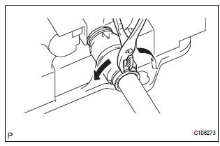
1. REMOVE NO. 2 FRONT AXLE INBOARD JOINT BOOT LH CLAMP
(a) Using pliers, remove the No. 2 front axle inboard joint boot LH clamp, as shown in the illustration.
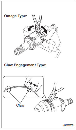
2. REMOVE FRONT AXLE INBOARD JOINT BOOT LH CLAMP
(a) Remove the front axle inboard joint boot LH clamp using the same procedures as for the No. 2 front axle inboard joint boot LH clamp.
3. SEPARATE FR AXLE INBOARD JOINT BOOT
(a) Separate the inboard joint boot from the inboard joint assembly.
4. REMOVE FRONT DRIVE INBOARD JOINT ASSEMBLY LH
(a) Remove the grease from the inboard joint.
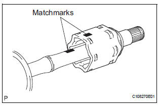
(b) Put matchmarks on the inboard joint shaft assembly and outboard joint shaft.
NOTICE: Do not use a punch for the marks.
(c) Remove the inboard joint shaft assembly from the outboard joint shaft.
(d) Using a snap ring expander, remove the snap ring.
(e) Put matchmarks on the outboard joint shaft and tripod.
NOTICE: Do not use a punch for the marks.
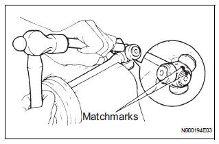
(f) Using a brass bar and hammer, remove the tripod from the outboard joint shaft.
NOTICE: Do not tap the roller.
5. REMOVE FR AXLE INBOARD JOINT BOOT
(a) Remove the inboard joint boot and inboard joint boot clamp.
6. REMOVE FRONT DRIVE SHAFT DAMPER CLAMP
(a) Using pliers, remove the front drive shaft damper clamp, as shown in the illustration.
7. REMOVE FRONT DRIVE SHAFT DAMPER
(a) Remove the drive shaft damper.
8. REMOVE OUTBOARD JOINT BOOT NO. 2 CLAMP
(a) Using pliers, remove the outboard joint boot No. 2 clamp, as shown in the illustration.
9. REMOVE OUTBOARD JOINT BOOT CLAMP
(a) Remove the outboard joint boot clamp perform the same procedures as for the outboard joint boot No.
2 clamp.
10. REMOVE OUTBOARD JOINT BOOT
(a) Remove the outboard joint boot from the outboard joint shaft.
(b) Remove the grease from the outboard joint.
11. REMOVE FRONT DRIVE SHAFT LH HOLE SNAP RING
(a) Using a screwdriver, remove the front drive shaft LH hole snap ring.
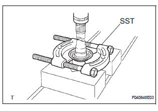
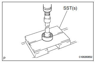
12. REMOVE FRONT DRIVE SHAFT DUST COVER LH
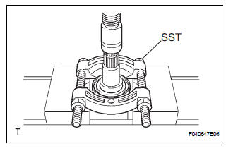
(a) Using SST and a press, remove the drive shaft dust cover LH.
SST 09950-00020
NOTICE: Be careful not to drop the inboard joint assembly.
13. REMOVE FRONT DRIVE SHAFT DUST COVER RH (for 2WD)
(a) Using a press, remove the drive shaft dust cover RH.
14. REMOVE FRONT DRIVE SHAFT DUST COVER RH (for 4WD)
(a) Using SST and a press, remove the drive shaft dust cover RH.
SST 09950-00020
NOTICE: Be careful not to drop the inboard joint assembly.
15. REMOVE FRONT DRIVE SHAFT DUST COVER
(a) Using SST and a press, remove the drive shaft dust cover.
SST 09950-00020
NOTICE: Be careful not to drop the inboard joint assembly.
16. REMOVE FRONT DRIVE SHAFT RH HOLE SNAP RING
(a) Using a snap ring expander, remove the drive shaft RH hole snap ring.
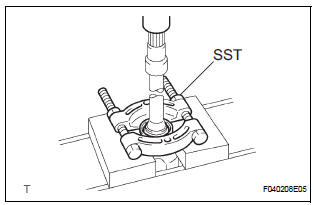
17. REMOVE FRONT DRIVE SHAFT BEARING
(a) Using SST and a press, remove the front drive shaft bearing.
SST 09527-10011
 Removal
1. Drain automatic transaxle fluid
(a) Remove the drain plug, gasket and drain ATF.
(b) Install a new gasket and the drain plug.
Torque: 49 N*m (500 kgf*cm, 36 ft.*lbf)
2. Drain transfer oil ( ...
 Inspection
1. INSPECT FRONT DRIVE SHAFT ASSEMBLY LH
(a) Check that there is no remarkable play in the radial
direction of the outboard joint.
(b) Check that the inboard joint slides smoothly in the
thr ...
Other materials:
Removal and installation of fuel control parts
(a) PLACE FOR REMOVING AND INSTALLING FUEL
SYSTEM PARTS
(1) Work in a location with good air ventilation that
does not have welders, grinders, drills, electric
motors, stoves, or any other ignition sources.
(2) Never work in a pit or near a pit as vaporized
fuel will collect in those places. ...
Inspection
1. INSPECT UNDERDRIVE PACK CLEARANCE
(a) Install the underdrive clutch to the transaxle case.
NOTICE:
Be careful not to damage the oil seal rings.
(b) Install a dial indicator as shown in the illustration.
(c) Measure the underdrive clutch pack clearance while
applying and releasing comp ...
Disassembly
1. REMOVE FRONT DIFFERENTIAL RING GEAR
(a) Place matchmarks on the front differential ring gear
and differential case.
(b) Remove the 14 bolts.
(c) Using a plastic hammer, tap on the front differential
ring gear to remove it from the case.
2. REMOVE FRONT DIFFERENTIAL CASE FRONT TA ...
