Toyota Sienna Service Manual: Inspection
1. INSPECT UNDERDRIVE PACK CLEARANCE
(a) Install the underdrive clutch to the transaxle case.
NOTICE: Be careful not to damage the oil seal rings.
(b) Install a dial indicator as shown in the illustration.
(c) Measure the underdrive clutch pack clearance while applying and releasing compressed air (392 kPa, 4.0 kgf/cm2, 57 psi).
Pack clearance: 1.51 to 1.71 mm (0.0594 to 0.0673 in.)
If the pack clearance is not as specified, inspect the discs, plates and flange.
HINT: There are 5 flanges in different thickness.
Flange thickness: mm (in.)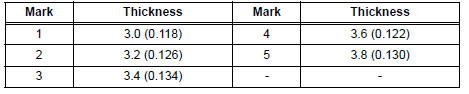
2. INSPECT UNDERDRIVE CLUTCH DISC NO.1
(a) Check if the sliding surface of the disc, plate and flange are worn or burnt. If necessary, replace them.
HINT:
- If the lining of the disc comes off or discolors, or if a part of the groove is worn, replace all discs.
- Before installing new discs, immerse them in ATF for at least 15 minutes.
3. INSPECT UNDERDRIVE CLUTCH DRUM SUBASSEMBLY
(a) Using a dial indicator, measure the inside diameter of the underdrive clutch drum bushing.
Standard drum bushing: 37.06 to 37.08 mm (1.4591 to 1.4598 in.) Maximum drum bushing: 37.13 mm (1.4618 in.)
If the inside diameter is greater than the maximum, replace the underdrive clutch drum.
4. INSPECT UNDERDRIVE CLUTCH RETURN SPRING SUB-ASSEMBLY
(a) Using a vernier calipers, measure the free length of the spring together with the spring seat.
Standard free length: 17.14 mm (0.6752 in.)
 Disassembly
1. INSPECT UNDERDRIVE PACK CLEARANCE
HINT:
(See page AX-262)
2. REMOVE UNDERDRIVE CLUTCH FLANGE NO.2 HOLE
SNAP RING
a) Using a screwdriver, remove the underdrive clutch
flange No.2 snap rin ...
 Reassembly
1. INSTALL UNDERDRIVE CLUTCH DRUM O-RING
(a) Coat a new O-ring with ATF, and install it to the
underdrive clutch drum.
NOTICE:
Make sure that the O-ring is not twisted or
pinched.
2. INSTALL ...
Other materials:
Disc cannot be Played/ No Playable Files/ Copyright Protection Error/ Disc
cannot be Played/ No Playable Files/ Copyright Protection Error
DTC 62-7D Disc cannot be Played
DTC 62-7E No Playable Files
DTC 62-7F Copyright Protection Error
DTC 63-7D Disc cannot be Played
DTC 63-7E No Playable Files
DTC 63-7F Copyright Protection Error
DESCRIPTION
INSPECTION PROCEDURE
HINT:
After the inspection is completed, clear the DTCs.
1 ...
Installation
1. INSTALL PARK/NEUTRAL POSITION SWITCH ASSEMBLY
(a) Install the park/neutral position switch to the manual
valve shaft.
(b) Temporarily install the 2 bolts.
(c) Place a new lock plate and tighten the nut.
Torque: 6.9 N*m (70 kgf*cm, 61 in.*lbf)
(d) Temporarily install the control ...
Camshaft Position "A" Actuator Circuit
DTC P0010 Camshaft Position "A" Actuator Circuit (Bank
1)
DTC P0020 Camshaft Position "A" Actuator Circuit (Bank
2)
DESCRIPTION
The Variable Valve Timing (VVT) system includes the ECM, Oil Control Valve (OCV)
and VVT controller.
The ECM sends a target duty-cycle control ...
