Toyota Sienna Service Manual: Drive belt
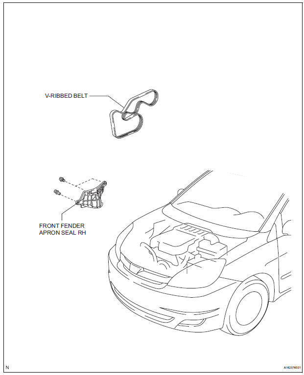
COMPONENTS
REMOVAL
1. REMOVE FRONT WHEEL RH
2. REMOVE FRONT FENDER APRON SEAL RH (See page EM-26)
3. REMOVE V-RIBBED BELT
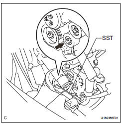
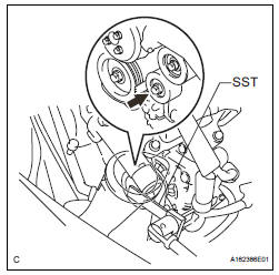
(a) Using SST, release the belt tension by turning the belt tensioner counterclockwise, and remove the Vribbed belt from the belt tensioner.
SST 09249-63010
(b) While turning the belt tensioner counterclockwise, align with its holes, and then insert the 5 mm bihexagon wrench into the holes to fix the V-ribbed belt tensioner.
INSPECTION
1. INSPECT V-RIBBED BELT
(a) Visually check the V-ribbed belt for excessive wear, frayed cords, etc.
If any defect has been found, replace the V-ribbed belt.
HINT:
Cracks on the rib side of a V-ribbed belt are considered acceptable.
If the drive belt has chunks missing from its ribs, it should be replaced.
HINT:
- A "new belt" is a belt which has been used for less than 5 minutes with the engine running.
- A "used belt" is a belt which has been used for 5 minutes or more with the engine running.
2. INSPECT V-RIBBED BELT TENSIONER ASSEMBLY
(a) Check that nothing gets caught in the tensioner by turning it clockwise and counterclockwise.
If a malfunction exitsts, replace the tensioner.
INSTALLATION
1. INSTALL V-RIBBED BELT
(a) Install the V-ribbed belt.
(b) Using SST, turn the belt tensioner counterclockwise and remove the bar.
SST 09249-63010
(c) If it is difficult to install the V-ribbed belt, perform the following procedure:
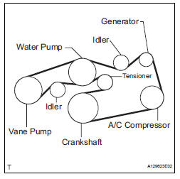
(1) Put the V-ribbed belt on every pulley except the tensioner pulley as shown in the illustration.
(2) While releasing the belt tension by turning the belt tensioner counterclockwise, put the Vribbed belt on the tensioner pulley.
NOTICE:
|
(3) After installing the V-ribbed belt, check that it fits properly in the ribbed grooves. Confirm that the belt has not slipped out of the grooves on the bottom of the crank pulley by hand.
2. INSTALL FRONT FENDER APRON SEAL RH (See page EM-62) 3. INSTALL FRONT WHEEL RH Torque: 103 N*m (1050 kgf*cm, 76 ft.*lbf)
 Engine
ON-VEHICLE INSPECTION
1. INSPECT ENGINE COOLANT
(a) Inspect the engine coolant (See page CO-1).
2. INSPECT ENGINE OIL
(a) Inspect the engine oil (See page LU-1).
3. INSPECT BATTERY
(a) Inspect t ...
 Engine front oil seal
COMPONENTS
REMOVAL
1. REMOVE FRONT WHEEL RH
2. REMOVE FRONT FENDER APRON SEAL RH (See
page EM-26)
3. REMOVE V-RIBBED BELT (See page EM-6)
4. REMOVE CRANKSHAFT PULLEY
(a) Using SST, loos ...
Other materials:
Reassembly
1. INSTALL NO. 1 SEAT CUSHION FRAME SUBASSEMBLY
Install the seat cushion frame with the bolt.
Torque: 20.6 N*m (210 kgf*cm, 15 ft.*lbf)
2. INSTALL RECLINING CONTROL LINK SUBASSEMBLY
Install the reclining control link with the E-ring.
Install the nut.
3. INSTALL RE ...
Disc cannot be Played/ No Playable Files/ Copyright Protection Error
DTC 63-7D Disc cannot be Played
DTC 63-7E No Playable Files
DTC 63-7F Copyright Protection Error
DESCRIPTION
DTC No.
DTC Detection Condition
Trouble Area
63-7D
An incompatible MP3 / WMA file is used.
Although the file has an extension of &quo ...
Yaw rate sensor check (when using sst check wire)
(a) Check the zero point voltage of the yaw rate sensor.
(1) Keep the vehicle in a stationary condition on a
level surface for 1 second or more.
(b) Check the output of the yaw rate sensor.
(1) Move the shift lever to the D position, drive the
vehicle at a speed of approximately 3 mph (5
...
