Toyota Sienna Service Manual: Dtc check / clear
1. DTC CHECK (SENSOR CHECK)
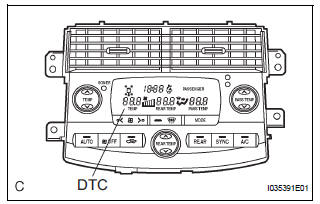
(a) After the indicator check is completed, the system enters the DTC check mode automatically.
(b) Read the codes displayed on the panel. Refer to the list of codes (See page AC-19) when reading the codes. (Trouble codes are output at the temperature display.)
(c) If the slower display is desired, press the DEF switch and change it to the step operation. Each time the DEF switch is pressed, the display changes by 1 step.
2. CLEARING DTC
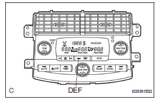
(a) To clear diagnostic trouble codes, there are 2 ways.
(1) During sensor check, press the "DEF" switch and "A/C" switch at the same time.
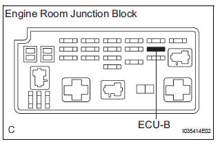
(2) Remove the ECU-B fuse in the engine room junction block for 20 seconds or longer to clear the DTC memory.
 Diagnosis system
1. CHECK DLC3
(a) The vehicle's ECM uses the ISO 15765-4 for
communication. The terminal arrangement of the
DLC3 complies with SAE J1962 and matches the
ISO 15765-4 format.
HINT:
Connect the ...
 Check mode procedure
1. LIST OF OPERATION METHODS
By operating each of the A/C control switches as shown
in the diagram below, it is possible to enter the diagnosis
check mode.
...
Other materials:
Removal
1. PRECAUTION
CAUTION:
Be sure to read "PRECAUTION" thoroughly before
servicing.
2. DISCONNECT CABLE FROM NEGATIVE BATTERY
TERMINAL
CAUTION:
Wait for 90 seconds after disconnecting the cable to
prevent the airbag working.
3. PLACE FRONT WHEELS FACING STRAIGHT AHEAD
4. REMOVE STEE ...
Unlock Warning Switch Circuit
DESCRIPTION
The unlock warning switch detects if the key is in the ignition key cylinder.
The unlock warning switch turns on when the key is inserted into the ignition
key cylinder and turns off
when the key is removed from the cylinder.
The body ECU is connected to the unlock warning swit ...
Short to B+ in Driver Side Squib 2nd Step Circuit
DTC B1183/22 Short to B+ in Driver Side Squib 2nd Step Circuit
DESCRIPTION
The driver side squib 2nd step circuit consists of the center airbag sensor
assembly, the spiral cable and
the steering pad.
The circuit instructs the SRS to deploy when deployment conditions are met.
DTC B1183/22 ...
