Toyota Sienna Service Manual: Unlock Warning Switch Circuit
DESCRIPTION
The unlock warning switch detects if the key is in the ignition key cylinder.
The unlock warning switch turns on when the key is inserted into the ignition key cylinder and turns off when the key is removed from the cylinder.
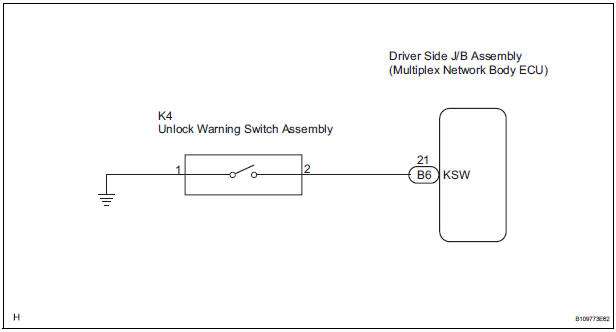
The body ECU is connected to the unlock warning switch via terminal KSW and key detection status signals are input to the ECU.
The body ECU applies voltage to the unlock warning switch via terminal KSW. When the unlock warning switch is on (there is continuity between the switch terminals), a signal indicating that the key is in the ignition key cylinder is input to the body ECU. When the switch is off (there is no continuity between the switch terminals), a signal indicating that the key is not in the cylinder is input.
WIRING DIAGRAM
INSPECTION PROCEDURE
1 READ VALUE OF DATA LIST (UNLOCK WARNING SWITCH)
- Check the DATA LIST to ensure proper function of the door unlock detection switch.
BODY:
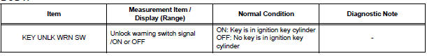
OK: The display is as specified in the normal condition.
PROCEED TO NEXT CIRCUIT INSPECTION SHOWN IN PROBLEM SYMPTOMS TABLE
2 INSPECT UNLOCK WARNING SWITCH ASSEMBLY
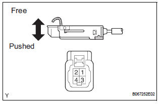
- Remove the unlock warning switch assembly.
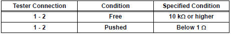
- Measure the resistance according to the value(s) in the table below.
Standard resistance
3 CHECK WIRE HARNESS (UNLOCK WARNING SWITCH - DRIVER SIDE J/B)
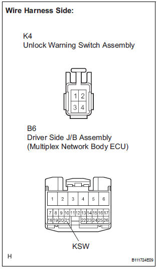
- Disconnect the K4 unlock warning switch assembly connector.
- Disconnect the B6 driver side J/B connector.
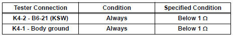
- Measure the resistance according to the value(s) in the table below.
Standard resistance
PROCEED TO NEXT CIRCUIT INSPECTION SHOWN IN PROBLEM SYMPTOMS TABLE
 Data list / active test
1. READ DATA LIST
HINT:
Using the intelligent tester's DATA LIST allows switch,
actuator and other item values to be read without
removing any parts. Reading the DATA LIST early in
troubleshootin ...
 Transmitter battery
REPLACEMENT
1. REMOVE TRANSMITTER BATTERY
NOTICE:
Special caution should be taken for handling each
component as they are precision electronic
components.
Using a coin or the equiva ...
Other materials:
Air Mix Damper Position Sensor Circuit (Passenger Side)
DESCRIPTION
This sensor detects the position of the air mix control servo motor (air mix
damper) and sends the
appropriate signals to the A/C amplifier. The position sensor is built in the
air mix control servo motor. The
position sensor's resistance changes as the air mix control servo m ...
Installation
1. REMOVE FRONT SEAT INNER BELT ASSEMBLY
HINT:
Refer to the instructions for reassembly of the front seat assembly
(for flat type).
Refer to the instructions for reassembly of the front seat assembly
(for manual seat).
Refer to the instructions for reassembly of the ...
Initialization
1. RESET
Reset the power slide door system:
The power slide door ECU records the fully open
position of the power slide door in its memory and
the power slide door fully opens and closes based
on this memory. The power slide door cannot
operate without this memory. In the case wh ...
