Toyota Sienna Service Manual: Front Fog Light Circuit
DESCRIPTION
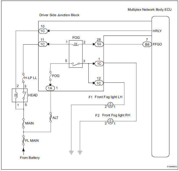
The Multiplex network body ECU controls FOG relay when signal is received from headlight dimmer switch assembly.
WIRING DIAGRAM
INSPECTION PROCEDURE
1 PERFORM ACTIVE TEST BY INTELLIGENT TESTER
- Connect the intelligent tester to DLC3.
- Turn the ignition switch ON and push the intelligent tester main switch ON.
- Select the item below in the ACTIVE TEST and then check that the relay operates.
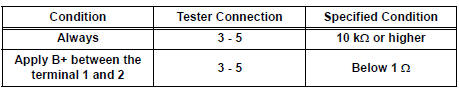
2 INSPECT FOG LIGHT RELAY
- Inspect fog light relay continuity.
Standard
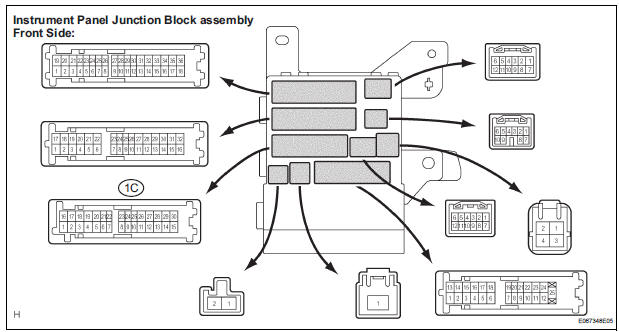
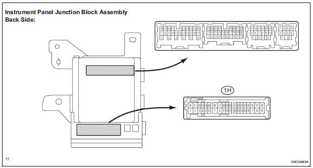
3 INSPECT INSTRUMENT PANEL JUNCTION BLOCK ASSEMBLY
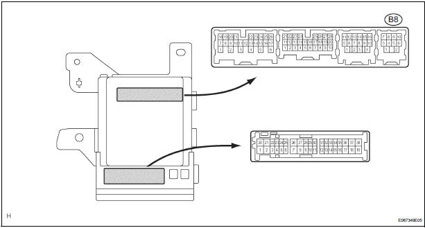
- Measure voltage between the terminal B8-7 of the multiplex network body ECU in the instrument panel junction block assembly and body ground.
Voltage
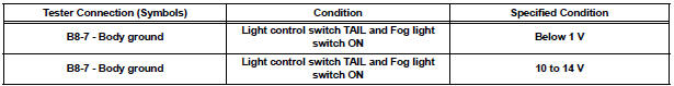
4 INSPECT INSTRUMENT PANEL JUNCTION BLOCK ASSEMBLY
- Remove the instrument panel junction block assembly.
- Measure voltage between each of the terminals as shown in the chart below.
Voltage

REPAIR OR REPLACE HARNESS OR CONNECTOR
 DRL Relay Circuit
DESCRIPTION
The Multiplex network body ECU controls the DRL No.2 relay
WIRING DIAGRAM
INSPECTION PROCEDURE
1 PERFORM ACTIVE TEST BY INTELLIGENT TESTER
Connect the intelligent tester to DLC ...
 Light Control Switch Circuit
DESCRIPTION
This circuit detects the state of the headlight dimmer switch.
WIRING DIAGRAM
INSPECTION PROCEDURE
1 READ VALUE OF INTELLIGENT TESTER
Connect the intelligent tester to DLC3.
...
Other materials:
Terminals of ECU
1. CHECK DRIVER SIDE J/B ASSEMBLY (MULTIPLEX NETWORK BODY ECU)
Disconnect the 1C, 1J, 1L, 1K, 1P, B6, B7 and B9 J/
B connectors.
Measure the voltage and resistance according to
the value(s) in the table below.
Standard
HINT:
If the result is not as specified ...
Short to B+ in Front Passenger Side Squib 2nd
Step Circuit
DTC B1188/56 Short to B+ in Front Passenger Side Squib 2nd
Step Circuit
DESCRIPTION
The front passenger side squib 2nd step circuit consists of the center airbag
sensor assembly and the
front passenger airbag assembly.
The circuit instructs the SRS to deploy when deployment conditions are m ...
Capacity and distribution
Cargo capacity depends on the total weight of the occupants.
(Cargo capacity) = (Total load capacity) - (Total weight of occupants)
Steps for Determining Correct Load Limit
Locate the statement “The combined weight of occupants and
cargo should never exceed XXX kg or XXX lbs.” on your ...
