Toyota Sienna Service Manual: Inspection
1. INSPECT OIL PUMP ASSEMBLY
(a) Turn the drive gear with the 2 screwdrivers and make sure that it rotates smoothly.
| NOTICE: Be careful not to damage the oil seal lip. |
2. INSPECT CLEARANCE OF OIL PUMP ASSEMBLY
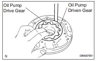
(a) Push the driven gear to one side of the body.
(b) Using a feeler gauge, measure the clearance.
Standard body clearance: 0.10 to 0.17 mm (0.0039 to 0.0067 in.) Side clearance: 0.02 to 0.05 mm (0.001 to 0.002 in.) Maximum body clearance: 0.17 mm (0.0067 in.)
If the body clearance is greater than the maximum, replace the oil pump body sub-assembly.
(c) Using a feeler gauge, measure the tip clearance between the driven gear teeth and drive gear teeth.
Standard tip clearance: 0.07 to 0.15 mm (0.0028 to 0.0059 in.) Maximum tip clearance: 0.15 mm (0.0059 in.)
If the tip clearance is greater than the maximum, replace the oil pump body sub-assembly.
(d) Using a straightedge and feeler gauge, measure the side clearance of both gears.
Standard side clearance: 0.02 to 0.05 mm (0.0008 to 0.0020 in.) Maximum side clearance: 0.05 mm (0.0020 in.)
Drive gear thickness: mm (in.) 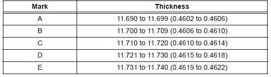
Driven gear thickness: mm (in.)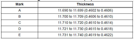
3. INSPECT FRONT OIL PUMP AND GEAR BODY SUBASSEMBLY
(a) Using a dial indicator, measure the inside diameter of the oil pump body bushing.
Standard inside diameter: 38.113 to 38.138 mm (1.50051 to 1.50149 in.) Maximum inside diameter: 38.188 mm (1.50346 in.)
If the inside diameter is greater than the maximum, replace the oil pump body sub-assembly.
4. INSPECT STATOR SHAFT ASSEMBLY
(a) Using a dial indicator, measure the inside diameter of the stator shaft.
Standard inside diameter: 21.500 to 21.526 mm (0.84646 to 0.84748 in.) Maximum inside diameter: 21.57 mm (0.8492 in.)
If the inside diameter is greater than the maximum, replace the stator shaft.
 Disassembly
1. INSPECT OIL PUMP ASSEMBLY
HINT:
(See page AX-234)
2. REMOVE CLUTCH DRUM OIL SEAL RING
(a) Remove the 2 clutch drum oil seal rings.
3. REMOVE STATOR SHAFT ASSEMBLY
(a) Using a "torx&q ...
 Reassembly
1. INSTALL FRONT OIL PUMP OIL SEAL
(a) Using SST and a hammer, install a new oil seal to
the oil pump body.
SST 09350-32014 (09351-32140)
HINT:
The seal end should be flat with the outer edge ...
Other materials:
Cruise Main Indicator Light Circuit
DESCRIPTION
The ECM detects a cruise control switch signal and sends it to the
combination meter through CAN
and BEAN. Then the CRUISE main indicator light comes on.
The CRUISE main indicator light circuit uses CAN and BEAN for
communication. If there is a
malfunction in ...
Ambient temperature sensor
ON-VEHICLE INSPECTION
1. INSPECT A/C AMBIENT TEMPERATURE SENSOR
(a) Remove the A/C ambient temperature sensor.
(b) Disconnect the connector from A/C ambient
temperature sensor.
(c) Measure the resistance according to the value(s) in
the table below.
Standard resistance
NOTICE:
E ...
Short to B+ in Curtain Shield Squib LH Circuit
DTC B1168/86 Short to B+ in Curtain Shield Squib LH Circuit
DESCRIPTION
The curtain shield squib LH circuit consists of the center airbag sensor
assembly and the curtain shield
airbag assembly LH.
The circuit instructs the SRS to deploy when deployment conditions are met.
DTC B1168/86 is ...
