Toyota Sienna Service Manual: Disassembly
1. INSPECT OIL PUMP ASSEMBLY
HINT: (See page AX-234)
2. REMOVE CLUTCH DRUM OIL SEAL RING
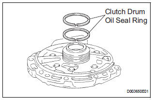
(a) Remove the 2 clutch drum oil seal rings.
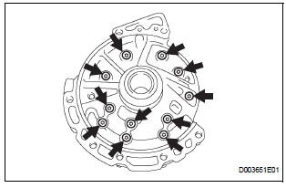
3. REMOVE STATOR SHAFT ASSEMBLY
(a) Using a "torx" socket (T30), remove the 11 bolts and stator shaft.
4. INSPECT CLEARANCE OF OIL PUMP ASSEMBLY
HINT: (See page AX-234)
5. REMOVE FRONT OIL PUMP DRIVE GEAR
(a) Remove the front oil pump drive gear.
6. REMOVE FRONT OIL PUMP DRIVEN GEAR
(a) Remove the front oil pump driven gear.
7. REMOVE FRONT OIL PUMP BODY O-RING
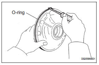
(a) Using a screwdriver, remove the O-ring.
HINT: Tape the screwdriver before use.
8. REMOVE FRONT OIL PUMP OIL SEAL
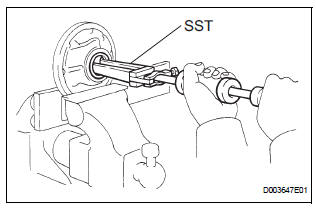
(a) Mount the oil pump in a soft jaw vise.
(b) Using SST, remove the oil seal from the oil pump body.
SST 09308-00010
 Oil pump
COMPONENTS
...
 Inspection
1. INSPECT OIL PUMP ASSEMBLY
(a) Turn the drive gear with the 2 screwdrivers and
make sure that it rotates smoothly.
NOTICE:
Be careful not to damage the oil seal lip.
2. INSPEC ...
Other materials:
EVAP System
RELATED DTCS
If any EVAP system DTCs are set, the malfunctioning area can be determined
using the table below.
NOTICE:
If the 0.02 inch reference pressure difference between the first and
second checks is greater than
the specification, the DTCs corresponding to the refe ...
Removal
1. REMOVE ENGINE ASSEMBLY WITH TRANSAXLE
HINT:
(See page EM-26)
2. REMOVE FRONT DRIVE SHAFT ASSEMBLY LH
HINT:
(See page DS-6)
3. REMOVE FRONT DRIVE SHAFT ASSEMBLY RH
HINT:
(See page DS-6)
4. REMOVE TRANSMISSION CONTROL CABLE CLAMP
(a) Remove the bolt and the transmission control cable
cla ...
Installation
1. INSTALL INTEGRATION CONTROL AND PANEL
ASSEMBLY
2. INSTALL RADIO RECEIVER WITH BRACKET (w/
Navigation System)
3. INSTALL RADIO RECEIVER WITH BRACKET (w/o
Navigation System)
4. INSTALL INSTRUMENT CLUSTER FINISH PANEL
GARNISH
5. INSTALL INSTRUMENT CLUSTER FINISH PANEL
ASSEMBLY CENTER
6. IN ...
