Toyota Sienna Service Manual: Installation
1. INSTALL STEERING COLUMN ASSEMBLY
(a) Install the steering column assembly with the 3 bolts.
Torque: 25 N*m (255 kgf*cm, 18 ft.*lbf) (b) Connect the connectors.
(c) Connect the wire harness clamps to the steering column tube.
2. CONNECT STEERING INTERMEDIATE SHAFT ASSEMBLY
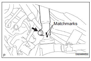
(a) Align the matchmarks on the intermediate shaft assembly and steering gear assembly.
(b) Install the steering intermediate shaft assembly with the bolt.
Torque: 36 N*m (370 kgf*cm, 27 ft.*lbf)
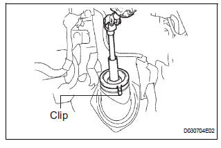
(c) Install the dust cover to the hole cover. Check that the 3 clips of the dust cover are securely fitted into the groove on the hole cover.
3. PLACE FRONT WHEELS FACING STRAIGHT AHEAD
4. INSTALL SPIRAL CABLE SUB-ASSEMBLY (See page RS-434)
5. INSTALL STEERING COLUMN COVER
6. CENTER SPIRAL CABLE (See page RS-435)
7. INSTALL STEERING WHEEL ASSEMBLY
(a) Align the matchmarks on the steering wheel assembly and steering main shaft assembly.
(b) Install the steering wheel assembly set nut.
Torque: 50 N*m (510 kgf*cm, 37 ft.*lbf) (c) Connect the connector.
8. INSPECT STEERING WHEEL CENTER POINT
9. INSPECT HORN BUTTON ASSEMBLY (See page RS- 425)
10. INSTALL HORN BUTTON ASSEMBLY (See page RS- 424)
11. INSTALL STEERING WHEEL COVER LOWER NO.3 (See page RS-425)
12. INSTALL STEERING WHEEL COVER LOWER NO.2 (See page RS-425)
13. CONNECT BATTERY NEGATIVE TERMINAL
14. INSPECT SRS WARNING LIGHT (See page RS-436)
 Reassembly
1. INSTALL IGNITION OR STARTER SWITCH
ASSEMBLY
(a) Install the ignition or starter switch assembly to the
steering column bracket assembly UPR with the 2
screws.
2. INSTALL KEY INTER LOCK SOLENOI ...
 Power steering
...
Other materials:
Short to GND in Driver Side Squib Circuit
DTC B0102/11 Short to GND in Driver Side Squib Circuit
DESCRIPTION
The driver side squib circuit consists of the center airbag sensor assembly,
the spiral cable and the
steering pad.
The circuit instructs the SRS to deploy when deployment conditions are met.
DTC B0102/11 is recorded when ...
Removal
1. REMOVE GLOVE COMPARTMENT DOOR STOPPER
SUB-ASSEMBLY
2. REMOVE GLOVE COMPARTMENT DOOR
ASSEMBLY
3. REMOVE STEREO COMPONENT AMPLIFIER
ASSEMBLY (W/ STEREO COMPONENT AMPLIFIER)
4. REMOVE DISTANCE CONTROL ECU ASSEMBLY
Remove the bolt.
Disengage the clip and remove the distanc ...
Mirror Switch Circuit
DESCRIPTION
A switch signal of the outer mirror switch is transmitted to the
selected outer mirror control ECU by way
of the body ECU. Then, the outer mirror control ECU activates the mirror
motor to move the mirror UP,
DOWN, RIGHT and LEFT in response to the inputs.
HINT:
Th ...
