Toyota Sienna Service Manual: Reassembly
1. INSTALL IGNITION OR STARTER SWITCH ASSEMBLY
(a) Install the ignition or starter switch assembly to the steering column bracket assembly UPR with the 2 screws.
2. INSTALL KEY INTER LOCK SOLENOID
(a) Install the solenoid to the steering column bracket assembly with the 2 screws.
3. INSTALL UN-LOCK WARNING SWITCH ASSEMBLY
(a) Install the un-lock warning switch assembly.
(b) Connect terminals 1 and 2 of the un-lock warning switch assembly connector.
(c) Connect the un-lock warning switch assembly connector to the ignition or starter switch assembly.
4. INSTALL IGNITION SWITCH LOCK CYLINDER ASSEMBLY
(a) Make sure that the ignition switch lock cylinder assembly is in the ACC position.
(b) Install the ignition switch lock cylinder assembly.
5. INSTALL STEERING LOCK OPERATION
(a) Check that the steering lock mechanism is activated when removing the key.
(b) Check that the steering lock mechanism is deactivated when inserting the key and turning it to the ACC position
6. INSTALL STEERING COLUMN BRACKET ASSEMBLY UPPER
(a) Temporarily install the steering column upper w/ switch bracket assembly and steering column upper clamp with 2 new tapered-head bolts.
(b) Tighten the 2 tapered-head bolts until the bolt heads break off.
7. INSTALL KEY CYLINDER LIGHT ASSEMBLY (w/o Engine Immobiliser System)
8. INSTALL TRANSPONDER KEY AMPLIFIER (w/ Engine Immobiliser System)
(a) Align the transponder key amplifier with the installation position of the upper bracket with the amplifier inclined.
(b) Push the transponder key amplifier up and connect it to the upper bracket.
NOTICE: Take care not to push the amplifier up with excessive force to prevent it from being damaged.
9. INSTALL STEERING INTERMEDIATE SHAFT ASSEMBLY
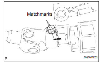
(a) Align the matchmarks on the steering intermediate shaft assembly and main shaft.
(b) Temporarily install the steering intermediate shaft assembly with the bolt.
Torque: 36 N*m (370 kgf*cm, 27 ft.*lbf)
 Disassembly
1. REMOVE STEERING INTERMEDIATE SHAFT ASSEMBLY
(a) Align the matchmarks on the steering intermediate
shaft assembly and main shaft.
(b) Remove the bolt and steering intermediate shaft
assemb ...
 Installation
1. INSTALL STEERING COLUMN ASSEMBLY
(a) Install the steering column assembly with the 3
bolts.
Torque: 25 N*m (255 kgf*cm, 18 ft.*lbf)
(b) Connect the connectors.
(c) Connect the wire har ...
Other materials:
Shift lock system
On-vehicle inspection
1. CHECK SHIFT LOCK OPERATION
(a) Move the shift lever to the P position.
(b) Turn the ignition switch to the LOCK position.
(c) Check that the shift lever cannot be moved to any
position other than P.
(d) Turn the ignition switch to the on position, depress
the br ...
Reassembly
1. INSTALL FRONT DRIVE SHAFT BEARING
(a) Using SST and a press, install a new front drive
shaft bearing.
SST 09710-30021 (09710-03141), 09527-10011
NOTICE:
Bearing should be completely installed.
2. INSTALL FRONT DRIVE SHAFT RH HOLE SNAP RING
(a) Using a snap ring expander, install a ...
Front stabilizer bar (for 4wd)
COMPONENTS
...
