Toyota Sienna Service Manual: Occupant Classification Sensor Power Supply Circuit Malfunction
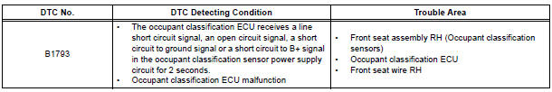
DTC B1793 Occupant Classification Sensor Power Supply Circuit Malfunction
DESCRIPTION
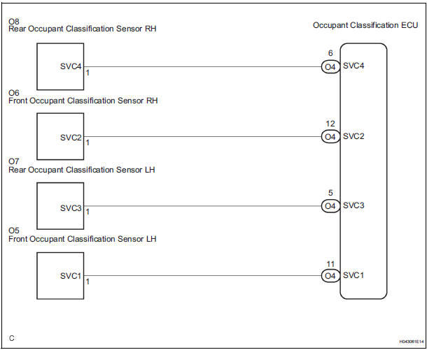
The occupant classification sensor power supply circuit consists of the occupant classification ECU and the occupant classification sensors.
DTC B1793 is recorded when a malfunction is detected in the occupant classification sensor power supply circuit
WIRING DIAGRAM
INSPECTION PROCEDURE
HINT:
- If troubleshooting (wire harness inspection) is difficult to perform, remove the front passenger seat installation bolts to see the under surface of the seat cushion.
- In the above case, hold the seat so that it does not fall down. Holding the seat for a long period of time may cause a problem, such as seat rail deformation. Hold the seat only as necessary.
1 CHECK DTC
- Turn the ignition switch to the ON position.
- Clear the DTCs stored in the memory.
HINT: First clear DTCs stored in the occupant classification ECU and then in the center airbag sensor assembly.
- Turn the ignition switch to the LOCK position.
- Turn the ignition switch to the ON position.
- Check the DTCs.
OK: DTC B1793 is not output.
HINT: Codes other than DTC B1793 may be output at this time, but they are not related to this check.
2 CHECK CONNECTION OF CONNECTORS
- Turn the ignition switch to the LOCK position.
- Disconnect the negative (-) terminal cable from the battery, and wait for at least 90 seconds.
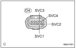
- Check that the connectors are properly connected to the occupant classification ECU and the occupant classification sensors.
OK: The connectors are properly connected.
3 CHECK FRONT SEAT WIRE RH (SHORT TO B+)
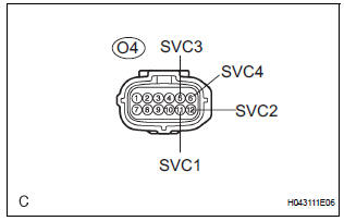
- Disconnect the connectors from the occupant classification ECU and the 4 occupant classification sensors.
- Connect the negative (-) terminal cable to the battery.
- Turn the ignition switch to the ON position.
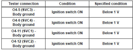
- Measure the voltage according to the value(s) in the table below.
Standard voltage
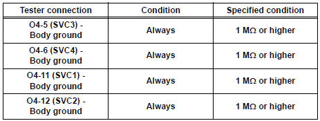
4 CHECK FRONT SEAT WIRE RH (SHORT TO GROUND)
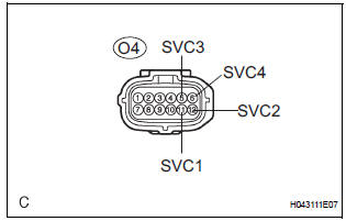
- Turn the ignition switch to the LOCK position.
- Disconnect the negative (-) terminal cable from the battery, and wait for at least 90 seconds.
- Measure the resistance according to the value(s) in the table below.
Standard resistance
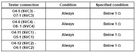
5 CHECK FRONT SEAT WIRE RH (OPEN)
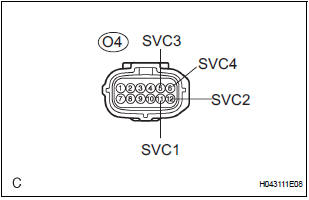
- Measure the resistance according to the value(s) in the table below.
Standard resistance
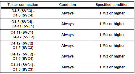
6 CHECK FRONT SEAT WIRE RH (SHORT)
- Measure the resistance according to the value(s) in the table below.
Standard resistance
7 CHECK DTC
- Connect the connectors to the occupant classification ECU and the 4 occupant classification sensors.
- Connect the negative (-) terminal cable to the battery.
- Turn the ignition switch to the ON position.
- Clear the DTCs stored in the memory
HINT: First clear DTCs stored in the occupant classification ECU and then in the center airbag sensor assembly. - Turn the ignition switch to the LOCK position.
- Turn the ignition switch to the ON position.
- Check the DTCs.
OK: DTC B1793 is not output.
HINT: Codes other than DTC B1793 may be output at this time, but they are not related to this check.
8 REPLACE OCCUPANT CLASSIFICATION ECU
- Turn the ignition switch to the LOCK position.
- Disconnect the negative (-) terminal cable from the battery, and wait for at least 90 seconds.
- Replace the occupant classification ECU.
HINT: Perform the inspection using parts from a normal vehicle if possible.
9 PERFORM ZERO POINT CALIBRATION
- Connect the negative (-) terminal cable to the battery.
- Connect the intelligent tester to the DLC3.
- Turn the ignition switch to the ON position.
- Using the intelligent tester, perform "Zero point calibration".
OK: "COMPLETED" is displayed.
10 PERFORM SENSITIVITY CHECK
- Using the intelligent tester, perform "Sensitivity check".
Standard value: 27 to 33 kg (59.52 to 72.75 lb)
11 CHECK DTC
- Turn the ignition switch to the ON position.
- Clear the DTCs stored in the memory.
HINT: First clear DTCs stored in the occupant classification ECU and then in the center airbag sensor assembly.
- Turn the ignition switch to the LOCK position.
- Turn the ignition switch to the ON position.
- Check the DTCs.
OK: DTC B1793 is not output.
HINT: Codes other than DTC B1793 may be output at this time, but they are related to this check.
12 REPLACE FRONT SEAT ASSEMBLY RH
- Turn the ignition switch to the LOCK position.
- Disconnect the negative (-) terminal cable from the battery, and wait for at least 90 seconds.
- Replace the front seat assembly RH ( for flat type, SE-48 for manual seat, SE-58 for power seat).
13 PERFORM ZERO POINT CALIBRATION
- Connect the negative (-) terminal cable to the battery.
- Connect the intelligent tester to the DLC3.
- Turn the ignition switch to the ON position.
- Using the intelligent tester, perform "Zero point calibration".
OK: "COMPLETED" is displayed.
14 PERFORM SENSITIVITY CHECK
- Using the intelligent tester, perform "Sensitivity check".
Standard value: 27 to 33 kg (59.52 to 72.75 lb)
END
 Center Airbag Sensor Assembly Communication
Circuit Malfunction
Center Airbag Sensor Assembly Communication
Circuit Malfunction
DTC B1790 Center Airbag Sensor Assembly Communication
Circuit Malfunction
DESCRIPTION
The center airbag sensor assembly communication circuit consists of the
occupant classification ECU and
the ...
 Open in Occupant Classification ECU Battery
Positive Line
Open in Occupant Classification ECU Battery
Positive Line
DTC B1794 Open in Occupant Classification ECU Battery
Positive Line
DESCRIPTION
This circuit consists of the occupant classification ECU and the power source
circuit (battery, fuse, wire
harness ...
Other materials:
Taillight Relay Circuit
DESCRIPTION
The Multiplex network body ECU controls TAIL relay when signal is received
from headlight dimmer
switch assembly.
WIRING DIAGRAM
INSPECTION PROCEDURE
1 PERFORM ACTIVE TEST BY INTELLIGENT TESTER
Connect the intelligent tester to DLC3.
Turn the ignition switch ON and ...
Oxygen (A/F) Sensor Signal Stuck
DTC P2195 Oxygen (A/F) Sensor Signal Stuck Lean (Bank 1
Sensor 1)
DTC P2196 Oxygen (A/F) Sensor Signal Stuck Rich (Bank 1
Sensor 1)
DTC P2197 Oxygen (A/F) Sensor Signal Stuck Lean (Bank 2
Sensor 1)
DTC P2198 Oxygen (A/F) Sensor Signal Stuck Rich (Bank 2
Sensor 1)
HINT:
Although the ...
Stereo Component Amplifier Power Source Circuit
DESCRIPTION
This circuit provides power to the stereo component amplifier.
WIRING DIAGRAM
INSPECTION PROCEDURE
1 INSPECT STEREO COMPONENT AMPLIFIER
Disconnect the stereo component amplifier connectors.
Measure the resistance according to the values in the
table below.
Standard ...
