Toyota Sienna Service Manual: Open in Stop Light Switch Circuit
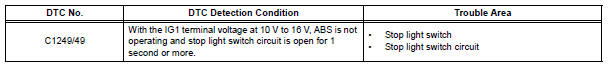
DTC C1249/49 Open in Stop Light Switch Circuit
DESCRIPTION
This skid control ECU inputs the stop light switch signal and detects the status of brake operation.
The skid control ECU has an open detection circuit. If an open in the stop light switch input line or GND side stop light circuit is detected when the stop light switch is off, this DTC is output.
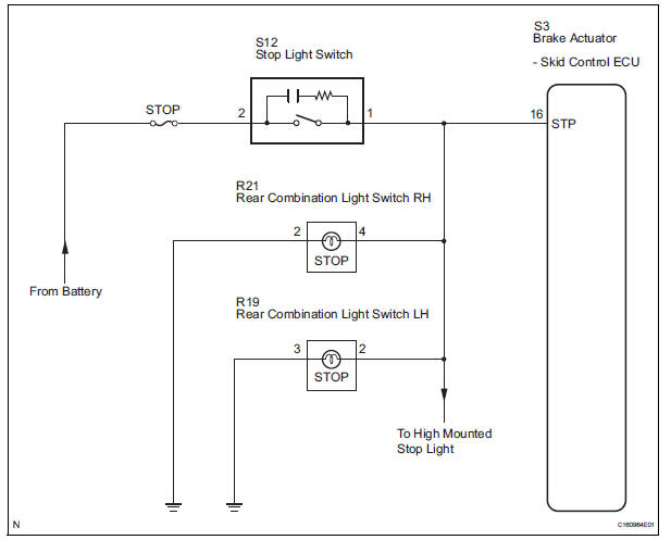
WIRING DIAGRAM
INSPECTION PROCEDURE
1 CHECK STOP LIGHT SWITCH OPERATION
(a) Check that the stop light comes on when the brake pedal is depressed, and goes off when the brake pedal is released.
OK: Stop light switch function is normal.
HINT: Check the stop light bulb as it may have burnt out.


2 INSPECT SKID CONTROL ECU (STP TERMINAL VOLTAGE)
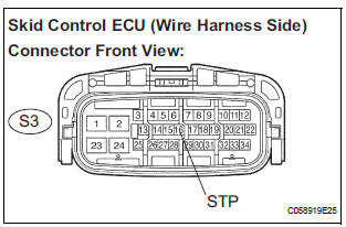
(a) Disconnect the skid control ECU connector.
(b) Measure the voltage according to the value(s) in the table below.
Standard voltage 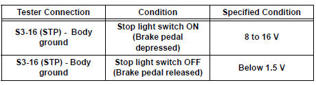
Result 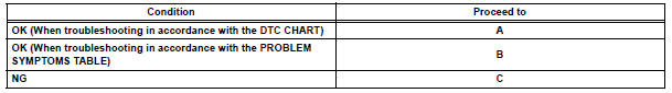

3 RECONFIRM DTC
(a) Clear the DTC (See page BC-10).
(b) Check that the same DTC is recorded (See page BC- 10).
HINT: Reinstall the sensors, connectors, etc. and restore the vehicle to its prior condition before rechecking for DTCs.
Result

REPLACE BRAKE ACTUATOR ASSEMBLY
4 INSPECT STOP LIGHT SWITCH (POWER SOURCE TERMINAL VOLTAGE)
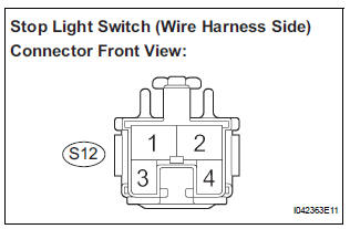
(a) Disconnect the stop light switch connector.
(b) Measure the voltage according to the value(s) in the table below.
Standard voltage 

5 INSPECT STOP LIGHT SWITCH
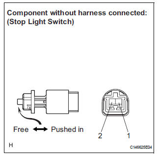
(a) Measure the resistance according to the value(s) in the table below.
Standard resistance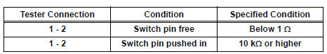


6 CHECK HARNESS AND CONNECTOR (BETWEEN SKID CONTROL ECU AND STOP LIGHT SWITCH)
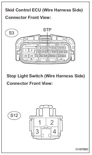
(a) Disconnect the skid control ECU connector.
(b) Measure the resistance according to the value(s) in the table below.
Standard resistance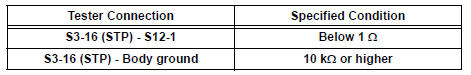
HINT:
- When troubleshooting in accordance with the DTC CHART, check DTCs before replacing the brake actuator assembly (See page BC-10).
- When troubleshooting in accordance with the PROBLEM SYMPTOMS TABLE, be sure to follow the table before replacing the brake actuator assembly (See page BC-7).

REPLACE BRAKE ACTUATOR ASSEMBLY
 Low Battery Positive Voltage
DTC C1241/41 Low Battery Positive Voltage
DESCRIPTION
If there is a problem with the brake actuator assembly (skid control ECU)
power supply circuit, the skid
control ECU outputs the DTC and proh ...
 Open in Pump Motor Circuit
DTC C1251/51 Open in Pump Motor Circuit
DESCRIPTION
The motor relay (semiconductor relay) is housed in the brake actuator
assembly and drives the pump
motor based on a signal from the skid contro ...
Other materials:
Reassembly
1. INSTALL UNDERDRIVE PLANETARY RING GEAR
HINT:
Use a torque wrench with a fulcrum length of 160
mm (6.3 in.).
(a) Install a new snap ring to the outer race of the radial
ball bearing rear.
HINT:
When replacing the bearing, also replace the
counter driven gear with a new one.
(b) Us ...
High Temperature
DTC 62-47 High Temperature
DTC 63-47 High Temperature
DESCRIPTION
DTC No.
DTC Detecting Condition
Trouble Area
62-47
Sensor detects that CD unit temperature is high. (Over
80C)
Radio receiver
63-47
Sensor detects that CD unit temperat ...
Fuel pump shut off
system
To minimize the risk of fuel leakage when the engine stalls or
when an airbag inflates upon collision, the fuel pump shut off
system stops the supply of fuel to the engine.
Follow the procedure below to restart the engine after the system is
activated.
Vehicles without a smart key system
...
