Toyota Sienna Service Manual: Open in Stop Light Switch Circuit
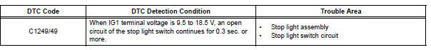
DTC C1249/49 Open in Stop Light Switch Circuit
DESCRIPTION
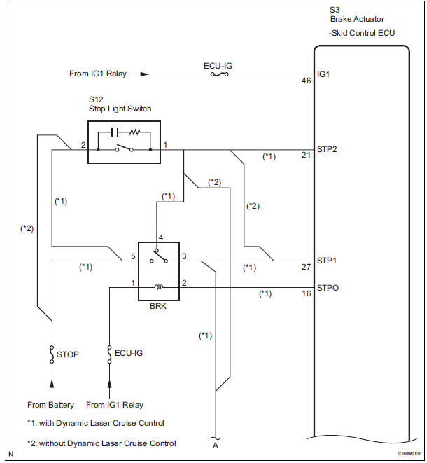
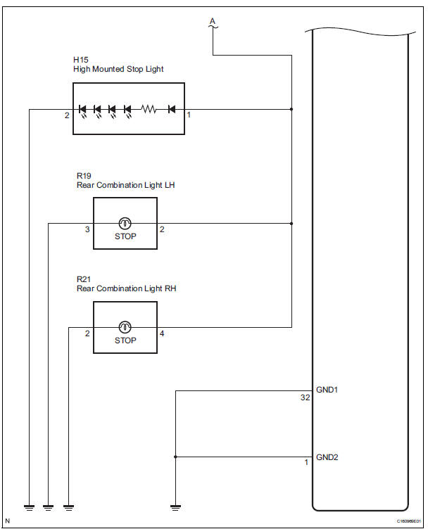
WIRING DIAGRAM
INSPECTION PROCEDURE
1 CHECK STOP LIGHT SWITCH OPERATION
(a) Check that the stop light comes on when the brake pedal is depressed and goes off when the brake pedal is released.
OK 
HINT: Check the stop light bulb as it may have burnt out.

2 INSPECT SKID CONTROL ECU (STP1 TERMINAL)
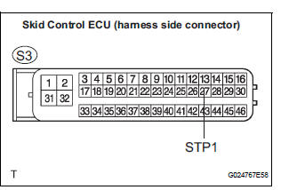
(a) Disconnect the skid control ECU connector.
(b) Measure the voltage according to the value(s) in the table below.
Standard voltage 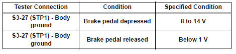

3 RECONFIRM DTC
(a) Clear the DTCs (See page BC-82).
(b) Turn the ignition switch to the ON position.
(c) Are the same DTCs detected?
Result 
NOTICE: When replacing the brake actuator assembly, perform zero point calibration (See page BC-70).

REPLACE BRAKE ACTUATOR ASSEMBLY
4 INSPECT STOP LIGHT SWITCH
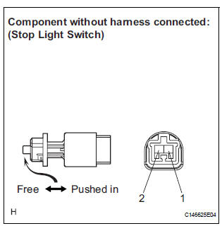
(a) Disconnect the stop light switch assembly connector.
(b) Measure the resistance according to the value(s) in the table below.
Standard resistance 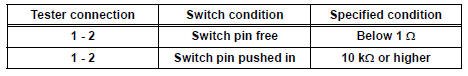

5 CHECK HARNESS AND CONNECTOR (STOP LIGHT SWITCH - SKID CONTROL ECU)
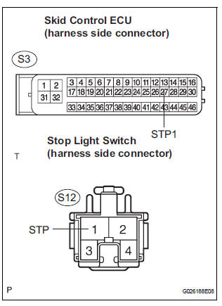
(a) Disconnect the stop light switch connector and skid control ECU connector.
(b) Measure the resistance according to the value(s) in the table below.
Standard resistance 
NOTICE: When replacing the brake actuator assembly, perform zero point calibration (See page BC-70).

REPLACE BRAKE ACTUATOR ASSEMBLY
 Master Cylinder Pressure Sensor Malfunction
DTC C1246/46 Master Cylinder Pressure Sensor Malfunction
DESCRIPTION
Master cylinder pressure sensor is connected to the skid control ECU in the
actuator.
INSPECTION PROCEDURE
1 READ VALUE O ...
 Open in Pump Motor Circuit
DTC C1251/51 Open in Pump Motor Circuit
DESCRIPTION
WIRING DIAGRAM
INSPECTION PROCEDURE
1 PERFORM ACTIVE TEST USING INTELLIGENT TESTER (ABS MOTOR RELAY)
(a) Connect the intelligent tester ...
Other materials:
Removal
1. REMOVE INSTRUMENT CLUSTER CENTER NO. 1 FINISH PANEL
2. REMOVE INSTRUMENT CLUSTER CENTER NO. 2
FINISH PANEL
3. REMOVE SHIFT LEVER KNOB SUB-ASSEMBLY
4. REMOVE POSITION INDICATOR HOUSING ASSEMBLY
5. REMOVE INSTRUMENT CLUSTER CENTER LOWER FINISH PANEL SUB-ASSEMBLY
6. REMOVE CIGARETTE LIGHTER CO ...
Data list / active test
1. READ DATA LIST
HINT:
Using the intelligent tester's DATA LIST allows switch,
actuator and other item values to be read without
removing any parts. Reading the DATA LIST early in
troubleshooting is one way to save time.
Connect the intelligent tester with CAN VIM to the
DLC3.
&n ...
Description of initialization
(a) Perform initialization in the following cases:
Before delivery of a new vehicle.
After replacement of the tire pressure warning
ECU*.
After replacement of the tire pressure warning
valve and transmitter.
Specified tire pressure changes depending on
the size or type of the tire.
...
