Toyota Sienna Service Manual: Park / Neutral Position Switch Circuit
DESCRIPTION
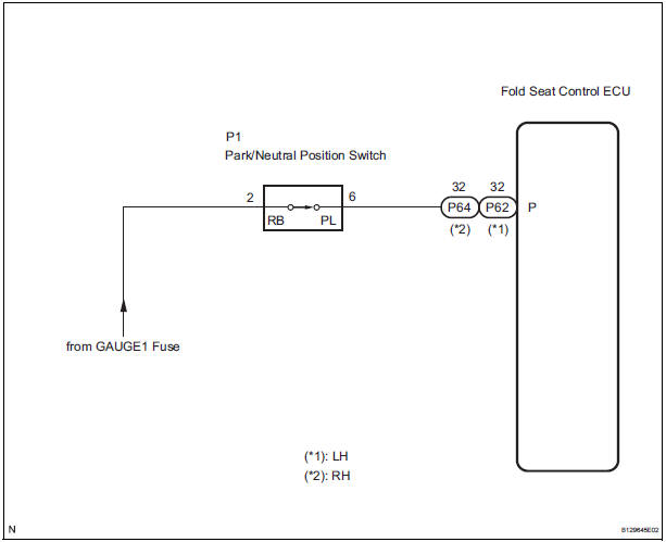
The fold seat control ECU receives signals from the Park/Neutral position switch and controls the seat stowing and return operations. If the shift lever is in any position other than P the seat cannot be operated.
If the ignition switch is in ACC or IG the seat cannot be operated.
WIRING DIAGRAM
INSPECTION PROCEDURE
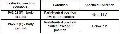
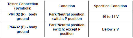
1 INSPECT FOLD SEAT CONTROL ECU
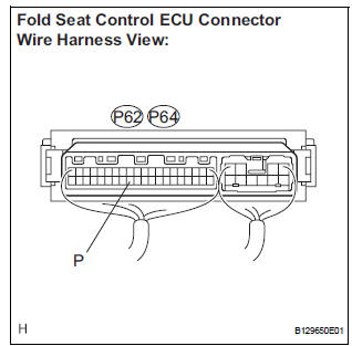
- Remove the fold seat control ECU with connectors still connected.
- Turn the ignition switch ON.
- Measure the voltage according to the value(s) in the table below.
Standard voltage: LH side
RH side
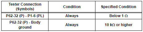
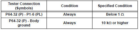
2 CHECK HARNESS AND CONNECTOR (FOLD SEAT CONTROL ECU - PARK/NEUTRAL POSITION SWITCH)
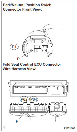
- Disconnect the connector from the park/neutral position switch.
- Disconnect the connectors from the fold seat control ECU.
- Measure the resistance according to the value(s) in the table below.
Standard resistance: LH side
RH side
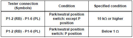
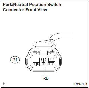
3 INSPECT PARK/NEUTRAL POSITION SWITCH
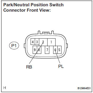
- Remove the park/neutral position switch.
- Measure the resistance according to the value(s) in the table below.
Standard resistance
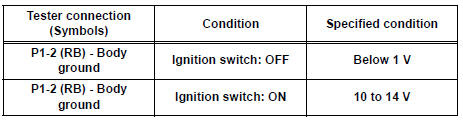
4 CHECK HARNESS AND CONNECTOR (PARK/NEUTRAL POSITION SWITCH - BATTERY)
- Measure the voltage according to the value(s) in the table below.
Standard voltage
REPLACE FOLD SEAT CONTROL ECU
 On-vehicle inspection
1. CHECK POWER REAR NO. 2 SEAT with STOWING FUNCTION
Check the basic functions.
Operate the fold seat switch and power rear
No.2 seat switch and check to make sure each
seat ...
 Back Door Courtesy Switch Circuit
DESCRIPTION
The fold seat control ECU receives signals from the back door courtesy switch
and detects the state of the
back door (open/close). If the ECU does not detect that the back door is open ...
Other materials:
Installation
1. INSTALL AMPLIFIER ANTENNA ASSEMBLY
Engage the 16 clamps to install the amplifier
antenna assembly.
Install the 3 bolts.
Connect the connectors.
2. INSTALL ROOF HEADLINING ASSEMBLY
3. INSTALL ANTENNA ASSEMBLY WITH HOLDER
Install the antenna assembly ...
Removal
1. REMOVE NO. 1 ENGINE UNDER COVER (See page
EM-26)
2. REMOVE EXHAUST PIPE ASSEMBLY
for 2WD:(See page EX-2)
for 4WD:(See page EX-8)
3. DRAIN ENGINE COOLANT (See page CO-6)
4. DRAIN ENGINE OIL (See page LU-4)
5. REMOVE NO. 2 MANIFOLD STAY (See page EM-39)
6. REMOVE NO. 2 EXHAUST MANIFOLD HEAT ...
Terminals of ECU
1. CENTER AIRBAG SENSOR ASSEMBLY (w/ Side
Airbag)
2. CENTER AIRBAG SENSOR ASSEMBLY (w/o Side
Airbag)
...
