Toyota Sienna Service Manual: Power Back Door does not Operate
DESCRIPTION
- The power back door operates only when the power back door main switch is ON. The power back door ECU controls the power back door by activating the back door motor (built into the power back door drive unit) to open / close the back door.
- A request signal from the satellite switch for power back door is input to the body ECU, which then sends this signal using a BEAN line to the power back door ECU so that the power back door is opened / closed.
- When a request signal is output from the satellite switch while the power back door is operating, the power back door reverses operation.
- If the power back door is manually moved in a specified distance when the back door is in the fully closed / opened position, the power back door will be activated and continue to operate to the fully opened / closed position.
- A request signal from the outside handle switch is directly input to the power back door ECU.
- Pulling the outside handle switch when the back door is in the fully closed position releases the latch of the closer and makes the back door not-fully-closed, which does not activate the power back door to open. (The power back door operation can be switched by customization.)
- When a request signal is output from the outside handle switch while the power back door is operating, the power back door reverses operation.
- When a request signal is output from the outside handle switch when the back door is in the fully open position, the power back door is activated to fully close. (Power back door operation can be changed by customization.)
- When the touch sensor has an open / short-circuit, closing of the power back door is disabled.
NOTICE: When disconnecting the negative (-) terminal cable of the battery or drive unit, initialize the power back door system
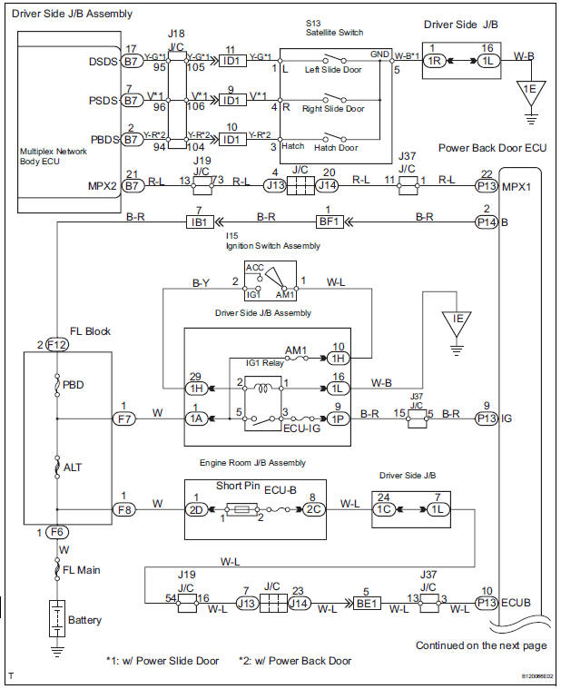
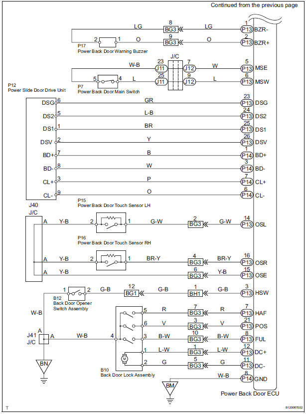
WIRING DIAGRAM
INSPECTION PROCEDURE
1 BASIC INSPECTION
- Conditions necessary for the power back door to open:
- Power back door main switch is in the ON position (switch free: orange paint on the top of the switch appears).
- Back door is between the fully closed position and approximately around the half-open position.
- Shift lever is in the P position when the ignition switch is ON (When the ignition switch is OFF, the power back door operates in any position of the shift lever.)
- Conditions necessary for the power back door to close:
- Power back door main switch is in the ON position (switch free: orange paint on the top of the switch appears).
- Back door is between approximately around the half-open position and the fully open position.
- Back door touch sensor is not damaged and deformed.
2 INSPECT FUSE (ECU-B, ECU IG, AM1)
- Inspect the ECU-B, ECU IG and AM1 fuses.
3 CHECK DTC
- Check for DTC B2222. DTC B2222 indicates a pulse sensor malfunction.
- Without code outputs, proceed to A.
- With code outputs, proceed to B.
4 INSPECT COMMUNICATION FUNCTION OF LARGE-SCALE MULTIPLEX COMMUNICATION SYSTEM (BEAN)
- Use the intelligent tester to check for normal function of the multiplex communication system.
- (ECU unconnected, communication line malfunctioning) Without DTC B1214, B1215 or B1287 outputs, proceed to A.
- (ECU unconnected, communication line malfunctioning) With DTC B1214, B1215 or B1287 outputs, proceed to B.
5 READ VALUE OF INTELLIGENT TESTER
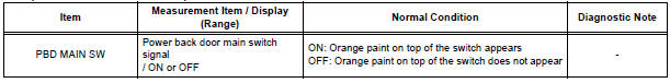
- Using the intelligent tester, check the DATA LIST for proper functioning of the power back door main switch.
OK (Power back door ECU):
6 INSPECT POWER BACK DOOR MAIN SWITCH
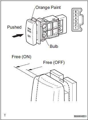
- Inspect the resistance of the main switch.
Resistance
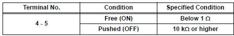
HINT: If the switch does not illuminate, it will not affect the ON / OFF function of the switch. For the illumination check, refer to INSPECTION
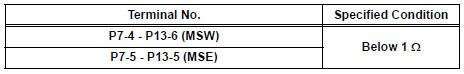
7 CHECK WIRE HARNESS (POWER BACK DOOR MAIN SWITCH - POWER BACK DOOR ECU)
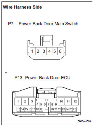
- Disconnect the P7 main switch and P13 ECU connectors.
- Check the resistance between the wire harness side connectors.
Resistance (Check for open circuit)
REPLACE POWER BACK DOOR ECU
8 CHECK SWITCH OPERATION
- If the power back door does not respond to using the satellite switch, proceed to A.
- If the power back door does not respond to using the back door opener switch outside, proceed to B.
9 INSPECT SATELLITE SWITCH
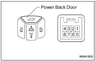
- Inspect the resistance of the back door switch.
Resistance
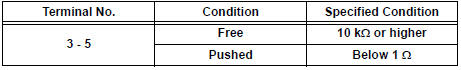
HINT: If the switch does not illuminate, it will not affect the ON / OFF function of the switch. For the illumination check, refer to INSPECTION
10 CHECK WIRE HARNESS (SATELLITE SWITCH - DRIVER SIDE J/B, BODY GROUND)
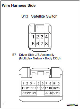
- Disconnect the S13 switch and the B7 ECU connectors.
- Check the resistance between the wire harness side connectors.
Resistance (Check for open circuit)
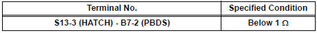
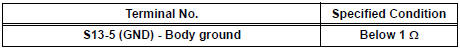
- Check the resistance between the S13 switch connector and body ground.
Resistance (Check for open circuit)
REPAIR OR REPLACE HARNESS AND CONNECTOR
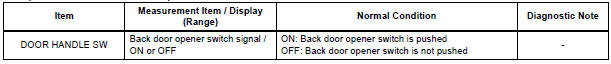
11 READ VALUE OF INTELLIGENT TESTER
- Using the intelligent tester, check the DATA LIST for proper functioning of the back door opener switch (Outside handle switch).
OK (Power back door ECU):
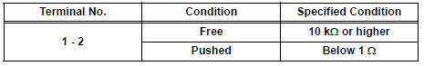
12 INSPECT BACK DOOR OPENER SWITCH ASSEMBLY (OUTSIDE HANDLE SWITCH)
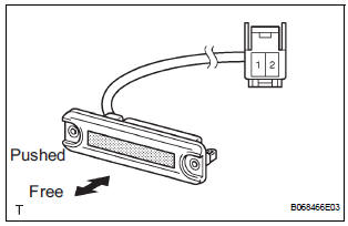
- Inspect the resistance of the switch.
Resistance
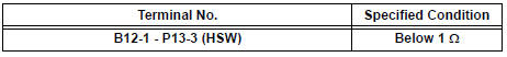
13 CHECK WIRE HARNESS (BACK DOOR OPENER SWITCH - POWER BACK DOOR ECU AND GROUND)
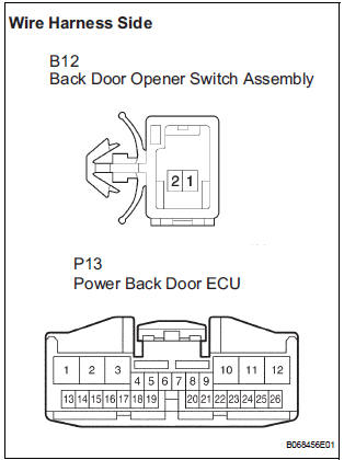
- Disconnect the B12 switch and P13 ECU connectors.
- Check the resistance between the wire harness side connectors.
Resistance (Check for open circuit)
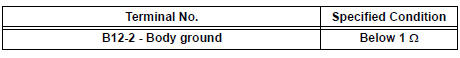
- Check the resistance between the B12 switch connector and body ground.
Resistance (Check for open circuit)
REPLACE POWER BACK DOOR ECU
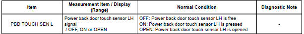
14 READ VALUE OF INTELLIGENT TESTER
- Using the intelligent tester, check the DATA LIST for proper functioning of the power back door touch sensor LH.
OK (Power back door ECU):
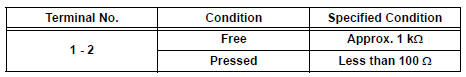
15 INSPECT POWER BACK DOOR TOUCH SENSOR LH
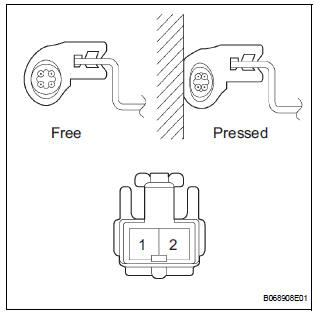
- Check the resistance of the sensor.
Resistance
16 CHECK WIRE HARNESS (POWER BACK DOOR TOUCH SENSOR LH - POWER BACK DOOR ECU)
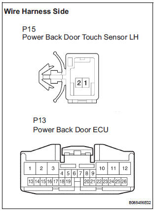
- Disconnect the P15 sensor and P13 ECU connectors.
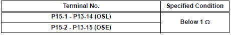
- Check the resistance between the wire harness side connectors.
Resistance (Check for open circuit)
REPLACE POWER BACK DOOR ECU
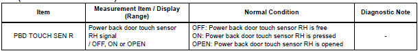
17 READ VALUE OF INTELLIGENT TESTER
- Using the intelligent tester, check the DATA LIST for proper functioning of the power back door touch sensor RH.
OK (Power back door ECU):
18 INSPECT POWER SLIDE DOOR WARNING BUZZER
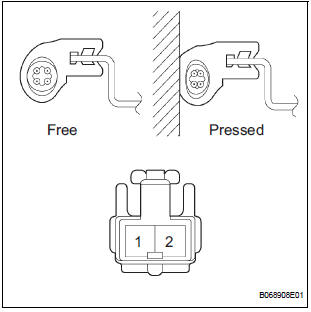
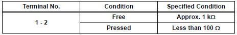
- Check the resistance of the sensor.
Resistance
19 CHECK WIRE HARNESS (POWER BACK DOOR TOUCH SENSOR RH - POWER BACK DOOR ECU)
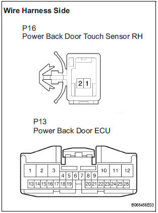
- Disconnect the P16 sensor and P13 ECU connectors.
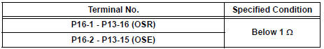
- Check the resistance between the wire harness side connectors.
Resistance (Check for open circuit)
REPLACE POWER BACK DOOR ECU
20 PERFORM ACTIVE TEST BY INTELLIGENT TESTER
- Select the ACTIVE TEST and then check that the power back door drive unit operates.
HINT: During the ACTIVE TEST, the intelligent tester sends a signal to the power back door ECU to drive the power back door drive unit. If the power back door drive unit operates, the power back door drive unit itself and the wire harness between the power back door drive unit and power back door ECU are considered to be functionary normally
OK (Power back door ECU):
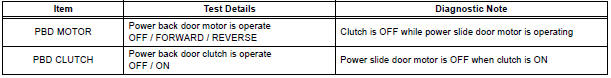
21 INSPECT POWER BACK DOOR DRIVE UNIT
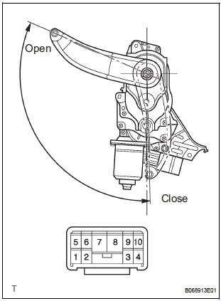
- Remove the unit.
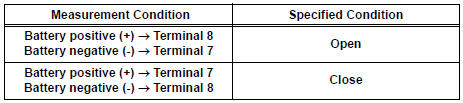
- Connect the battery positive (+) lead to terminal 3 and battery negative (-) terminal lead to terminal 9.
- Apply battery voltage to the terminals and check the motor operation.
OK
- Check the resistance of the clutch terminals.
Resistance
- Reinstall the unit with the connector connected.
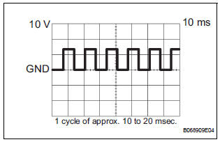
- Check the pulse of the pulse sensor.
- Using an oscilloscope, check the pulse generated when the door is manually opened and closed.
Reference
HINT: A cycle of the pulse changes between approx. 10 to 20 msec. according to the speeds that the slide door is moving.
NOTICE: When disconnecting the drive unit, initialize the power back door system
22 CHECK WIRE HARNESS (POWER BACK DOOR DRIVE UNIT - POWER BACK DOOR ECU)
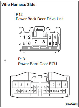
- Disconnect the P12 unit and P13 ECU connectors.
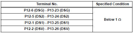
- Check the resistance between the wire harness side connectors.
Resistance (Check for open circuit)
REPLACE POWER BACK DOOR ECU
23 READ VALUE OF INTELLIGENT TESTER
- Using the intelligent tester, check the DATA LIST for proper functioning of the switches listed below.
OK (Power back door ECU):
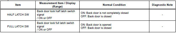
24 INSPECT BACK DOOR LOCK ASSEMBLY
25 CHECK WIRE HARNESS (BACK DOOR LOCK ASSEMBLY - POWER BACK DOOR ECU)
26 REPLACE POWER BACK DOOR ECU
- Check the power back door for normal OPEN / CLOSE operation
SYSTEM NORMAL
 PBD Pulse Sensor Malfunction
DTC B2222 PBD Pulse Sensor Malfunction
DESCRIPTION
A pulse sensor is built into the back door for a jam and foreign
object detection and for back door
position detection. The jam and foreign ...
 Jam Protection Function Activates During Power Back Door Operation
DESCRIPTION
It may be caused by ill-fitting back door, faulty touch sensor or
faulty pulse sensor.
The power back door ECU activates the back motor to open / close
the power back door, thu ...
Other materials:
Short in Rear Curtain Shield Squib RH Circuit
DTC B1630/83 Short in Rear Curtain Shield Squib RH Circuit
DESCRIPTION
The rear curtain shield squib RH circuit consists of the center airbag sensor
assembly and the curtain
shield airbag assembly RH.
The circuit instructs the SRS to deploy when deployment conditions are met.
DTC B1630/83 ...
Lumbar support adjuster assembly
INSPECTION
1. INSPECT LUMBAR SUPPORT ADJUSTER ASSEMBLY
Check operation of the lumbar support adjuster
motor.
Check if the lumbar support adjuster moves
smoothly when the battery is connected to the
lumbar support adjuster motor connector
terminal.
OK
If the r ...
Removal
1. REMOVE FRONT FENDER LINER LH
2. REMOVE FRONT FENDER LINER RH
3. REMOVE FRONT BUMPER COVER
4. REMOVE FRONT BUMPER ENERGY ABSORBER
5. REMOVE FRONT BUMPER REINFORCEMENT SUBASSEMBLY
6. REMOVE LASER SENSOR
Disconnect the connector and remove the laser the
sensor.
...
