Toyota Sienna Service Manual: Problem symptoms table
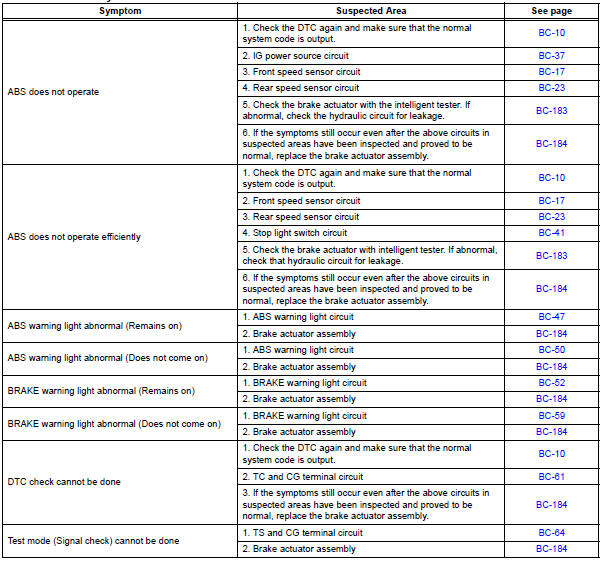
If there are no DTCs output but the problem still occurs, check the circuits for each problem symptom in the order given in the table below and proceed to the relevant troubleshooting page.
NOTICE: When replacing the brake actuator assembly, sensor, etc., turn the ignition switch off.
HINT: Inspect the fuse and relay before investigating the suspected areas as shown in the table below. Inspect each malfunction circuit in numerical order for the corresponding symptom.
Anti-lock brake system:
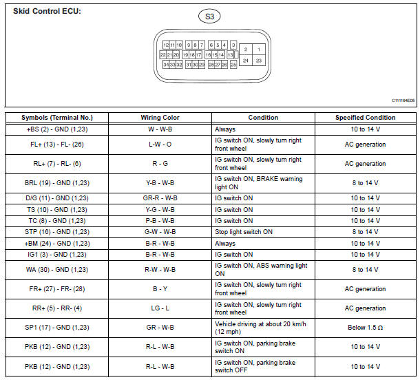
Terminals of ecu
 Test mode procedure
1. SPEED SENSOR SIGNAL CHECK (WHEN USING SST CHECK WIRE):
HINT:
If the ignition switch is turned from the ON to the ACC
or LOCK position during Test Mode, the DTCs of the
signal check functio ...
 Diagnosis system
1. DESCRIPTION
(a) Release the parking brake pedal.
(b) Check the warning lights.
When ignition switch is turned ON, check that the
ABS warning light and brake warning light come on
for 3 ...
Other materials:
ECM Power Source Circuit
DESCRIPTION
When the ignition switch is turned to the ON position, the battery voltage is
applied to terminal IGSW of
the ECM. The ECM MREL output signal causes a current to flow to the coil,
closing the contacts of the EFI
relay and supplying power to terminal +B of the ECM.
If the igniti ...
Removal
1. REMOVE INSTRUMENT PANEL SUB-ASSEMBLY WITH PASSENGER AIRBAG ASSEMBLY
HINT:
Refer to the instructions for removal of the instrument
panel sub-assembly w/ passenger airbag assembly (See
page IP-5).
2. REMOVE HEATER TO FOOT DUCT NO.1
(a) Remove the clip and the heater to foot duct No. 1.
3 ...
Installation
1. INSTALL REAR NO. 2 SEAT ASSEMBLY
Lock the seat leg rear to the floor striker.
Lock the seat leg front to the floor striker.
Install the rear No. 2 seat assembly with the 8 bolts.
Torque: 19 N*m (194 kgf*cm, 14 ft.*lbf)
NOTICE:
Tighten the bolts in the order sho ...
