Toyota Sienna Service Manual: Rear Occupant Classification Sensor LH Circuit Malfunction
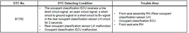
DTC B1782 Rear Occupant Classification Sensor LH Circuit Malfunction
DESCRIPTION
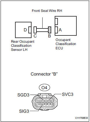
The rear occupant classification sensor LH circuit consists of the occupant classification ECU and the rear occupant classification sensor LH.
DTC B1782 is recorded when a malfunction is detected in the rear occupant classification sensor LH circuit.
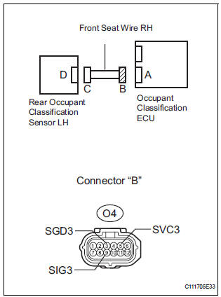
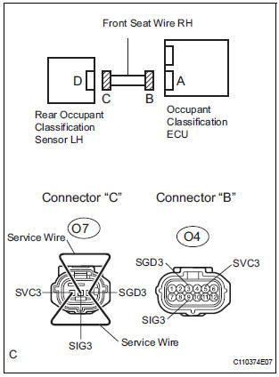
WIRING DIAGRAM
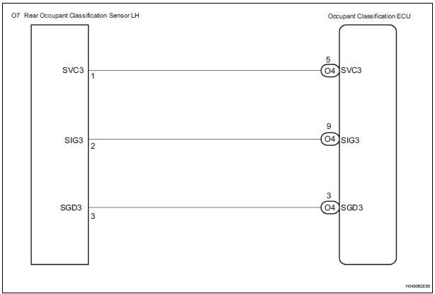
INSPECTION PROCEDURE
HINT:
- If troubleshooting (wire harness inspection) is difficult to perform, remove the front passenger seat installation bolts to see the under surface of the seat cushion.
- In the above case, hold the seat so that it does not fall down. Holding the seat for a long period of time may cause a problem, such as seat rail deformation. Hold the seat only as necessary.
1 CHECK DTC
- Turn the ignition switch to the ON position.
- Clear the DTCs stored in the memory.
HINT: First clear DTCs stored in the occupant classification ECU and then in the center airbag sensor assembly.
- Turn the ignition switch to the LOCK position.
- Turn the ignition switch to the ON position.
- Check the DTCs.
OK: DTC B1782 is not output.
HINT: Codes other than DTC B1782 may be output at this time, but they are not related to this check.
2 CHECK CONNECTION OF CONNECTORS
- Turn the ignition switch to the LOCK position.
- Disconnect the negative (-) terminal cable from the battery, and wait for at least 90 seconds.
- Check that the connectors are properly connected to the occupant classification ECU and the rear occupant classification sensor LH.
OK: The connectors are connected.
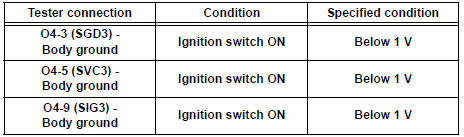
3 CHECK FRONT SEAT WIRE RH (SHORT TO B+)
- Disconnect the connectors from the occupant classification ECU and the rear occupant classification sensor LH.
- Connect the negative (-) terminal cable to the battery.
- Turn the ignition switch to the ON position.
- Measure the voltage according to the value(s) in the table below.
Standard voltage
4 CHECK FRONT SEAT WIRE RH (OPEN)
- Turn the ignition switch to the LOCK position.
- Disconnect the negative (-) terminal cable from the battery, and wait for at least 90 seconds.
- Using a service wire, connect O7-1 (SVC3) and O7-3
(SGD3), and connect O7-2 (SIG3) and O7-3 (SGD3) of
connector "C".
NOTICE: Do not forcibly insert a service wire into the terminals of the connector when connecting.
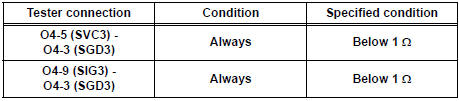
- Measure the resistance according to the value(s) in the table below.
Standard resistance
5 CHECK FRONT SEAT WIRE RH (SHORT)
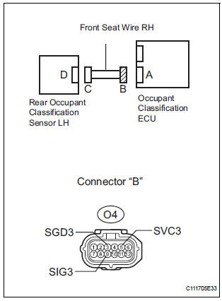
- Disconnect the service wire from connector "C".
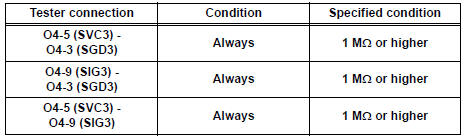
- Measure the resistance according to the value(s) in the table below.
Standard resistance
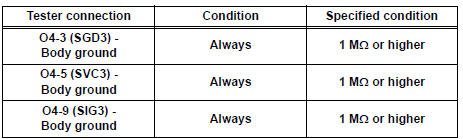
6 CHECK FRONT SEAT WIRE RH (SHORT TO GROUND)
- Measure the resistance according to value(s) in the table below.
Standard resistance
7 CHECK DTC
- Connect the connectors to the occupant classification ECU and the rear occupant classification sensor LH.
- Connect the negative (-) terminal cable to the battery.
- Turn the ignition switch to the ON position.
- Clear the DTCs stored in the memory.
HINT: First clear DTCs stored in the occupant classification ECU and then in the center airbag sensor assembly.
- Turn the ignition switch to the LOCK position.
- Turn the ignition switch to the ON position.
- Check the DTCs.
OK: DTC B1782 is not output.
HINT: Codes other than DTC B1782 may be output at this time, but they are not related to this check.
8 REPLACE OCCUPANT CLASSIFICATION ECU
- Turn the ignition switch to the LOCK position.
- Disconnect the negative (-) terminal cable from the battery, and wait for at least 90 seconds.
- Replace the occupant classification ECU.
HINT: Perform the inspection using parts from a normal vehicle if possible.
9 PERFORM ZERO POINT CALIBRATION
- Connect the negative (-) terminal cable to the battery.
- Connect the intelligent tester to the DLC3.
- Turn the ignition switch to the ON position.
- Using the intelligent tester, perform "Zero point calibration".
OK: "COMPLETED" is displayed
10 PERFORM SENSITIVITY CHECK
- Using the intelligent tester, perform "Sensitivity check".
Standard value: 27 to 33 kg (59.52 to 72.75 lb)
11 CHECK DTC
- Turn the ignition switch to the ON position.
- Clear the DTCs stored in the memory.
HINT: First clear DTCs stored in the occupant classification ECU and then in the center airbag sensor assembly.
- Turn the ignition switch to the LOCK position.
- Turn the ignition switch to the ON position.
- Check the DTCs.
OK: DTC B1782 is not output.
HINT: Codes other than DTC B1782 may be output at this time, but they are not related to this check.
12 REPLACE FRONT SEAT ASSEMBLY RH
- Turn the ignition switch to the LOCK position.
- Disconnect the negative (-) terminal cable from the battery, and wait for at least 90 seconds.
- Replace the front seat assembly RH ( for flat type, SE-48 for manual seat, SE-58 for power seat).
13 PERFORM ZERO POINT CALIBRATION
- Connect the negative (-) terminal cable to the battery.
- Connect the intelligent tester to the DLC3.
- Turn the ignition switch to the ON position.
- Using the intelligent tester, perform "Zero point calibration".
OK: "COMPLETED" is displayed.
14 PERFORM SENSITIVITY CHECK
- Using the intelligent tester, perform "Sensitivity check".
Standard value: 27 to 33 kg (59.52 to 72.75 lb)
END
 Front Occupant Classification Sensor RH Circuit
Malfunction
Front Occupant Classification Sensor RH Circuit
Malfunction
DTC B1781 Front Occupant Classification Sensor RH Circuit
Malfunction
DESCRIPTION
The front occupant classification sensor RH circuit consists of the occupant
classification ECU and the
front oc ...
 Rear Occupant Classification Sensor RH Circuit
Malfunction
Rear Occupant Classification Sensor RH Circuit
Malfunction
DTC B1783 Rear Occupant Classification Sensor RH Circuit
Malfunction
DESCRIPTION
The rear occupant classification sensor RH circuit consists of the occupant
classification ECU and the
rear occup ...
Other materials:
Air conditioning
SST
RECOMMENDED TOOLS
HINT:
Torx is a registered trademark of Textron Inc.
EQUIPMENT
LUBRICANT
SUPPLEMENTAL RESTRAINT SYSTEM
SST
RECOMMENDED TOOLS
HINT:
Torx is a registered trademark of Textron lnc.
EQUIPMENT
SEAT BELT
SST
RECOMMENDED TOOLS
EQUIPMENT
THEFT ...
Identification of noise source
1. Radio Description
Radio frequency band
Radio broadcasts use the radio frequency bands
shown in the table below.
Service area
The service areas of AM and FM broadcasts are
vastly different. Sometimes an AM broadcast
can be received very clearly ...
TC and CG Terminal Circuit
DESCRIPTION
DTC output mode is set by connecting terminals TC and CG of the DLC3.
The DTCs are displayed by the blinking pattern of the ABS warning light.
WIRING DIAGRAM
HINT:
When warning lights continue to blink, a ground short in the wiring of terminal
TC of the DLC3 or an
internal ...
