Toyota Sienna Service Manual: Reassembly
1. INSTALL UNDERDRIVE CLUTCH DRUM O-RING
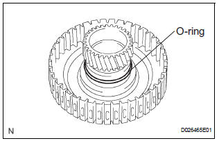
(a) Coat a new O-ring with ATF, and install it to the underdrive clutch drum.
NOTICE: Make sure that the O-ring is not twisted or pinched.
2. INSTALL UNDERDRIVE CLUTCH PISTON SET
(a) Coat the underdrive clutch piston with ATF, and install it to the underdrive clutch piston drum.
NOTICE:
- Be careful not to damage the O-ring.
- Be careful not to damage the lip of the piston.
3. INSTALL UNDERDRIVE CLUTCH RETURN SPRING SUB-ASSEMBLY
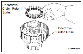
(a) Install the return spring to the underdrive clutch drum.
NOTICE: Installing the spring sub-assembly, check that all of the springs are fit in the piston correctly.
(b) Coat the clutch balancer with ATF.
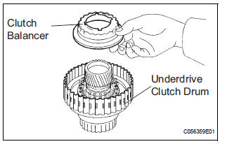
(c) Install the clutch balancer to the underdrive clutch drum.
NOTICE: Be careful not to damage the lip of the clutch balancer.
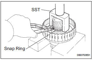
(d) Place SST on the clutch balancer and compress the piston return spring with a press.
SST 09350-32014 (09351-32070)
(e) Using a snap ring expander, install the snap ring to the underdrive clutch drum.
(f) Be sure that the end gap of the snap ring is not aligned with the spring retainer claw.
NOTICE:
- Stop the press when the spring seat is lowered to the place 1 to 2 mm (0.039 to 0.078 in.) from the snap ring groove.
- This prevents the spring seat from being deformed
- Do not expand the snap ring excessively.
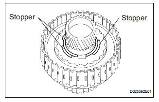
(g) Set the end gap of the snap ring in the underdrive clutch drum as shown in the illustration.
NOTICE: The end gap of the snap ring should not align with any of the stoppers.
4. INSTALL UNDERDRIVE CLUTCH DISC NO.1
(a) Coat the 4 discs with ATF.
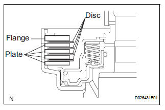
(b) Install the 4 plates, 4 discs and flange to the underdrive clutch drum.
NOTICE: Make sure that the plates, discs, and flange are installed as shown in the illustration.
5. INSTALL 1ST & REVERSE BRAKE RETURN SPRING SHAFT SNAP RING
(a) Using a screwdriver, install the underdrive clutch flange No.2 hole snap ring.
(b) Check that the end gap of snap ring is not aligned with one of the cutouts.
NOTICE: The snap ring should be fully engaged in the groove of the drum.
6. INSPECT UNDERDRIVE PACK CLEARANCE
HINT: (See page AX-262)
 Inspection
1. INSPECT UNDERDRIVE PACK CLEARANCE
(a) Install the underdrive clutch to the transaxle case.
NOTICE:
Be careful not to damage the oil seal rings.
(b) Install a dial indicator as shown in the ...
 Differential case
COMPONENTS
...
Other materials:
Correct use of the seat belts
Make sure that all occupants are wearing their seat belts before driving
the vehicle. Use a child restraint system appropriate for the child until the child
becomes large enough to properly wear the vehicle’s seat belt.
Adjusting the mirrors
Make sure that you can see backward clearly by adjus ...
Dtc clear
(A) when using the obd ii scan tool or intelligent
tester: clearing the dtcs.
(1) Connect the intelligent tester together with the
CAN VIM (controller area network vehicle
interface module) to the DLC3.
(2) Turn the ignition switch to the ON position and
turn the OBD II scan tool or the inte ...
Short to B+ in Front Passenger Side Squib 2nd
Step Circuit
DTC B1188/56 Short to B+ in Front Passenger Side Squib 2nd
Step Circuit
DESCRIPTION
The front passenger side squib 2nd step circuit consists of the center airbag
sensor assembly and the
front passenger airbag assembly.
The circuit instructs the SRS to deploy when deployment conditions are m ...
