Toyota Sienna Service Manual: Removal
1. PRECAUTION
HINT: See page RS-1
2. DISCONNECT BATTERY NEGATIVE TERMINAL
Wait for 90 seconds after disconnecting the battery terminal to prevent the airbag working.
3. PLACE FRONT WHEELS FACING STRAIGHT AHEAD
4. REMOVE STEERING WHEEL COVER LOWER NO.2 (See page RS-424)
5. REMOVE STEERING WHEEL COVER LOWER NO.3 (See page RS-424)
6. REMOVE HORN BUTTON ASSEMBLY (See page RS- 424)
7. REMOVE STEERING WHEEL ASSEMBLY
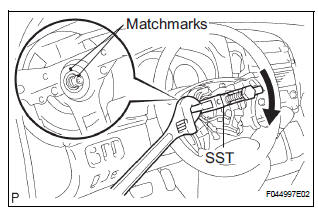
(a) Remove the steering wheel assembly set nut.
(b) Put matchmarks on the steering wheel assembly and main shaft assembly.
(c) Using SST, remove the steering wheel assembly.
SST 09950-50013 (09951-05010, 09952-05010, 09953-05020, 09954-05021)
8. REMOVE STEERING COLUMN COVER
(a) Remove the 2 screws and steering column cover.
9. REMOVE SPIRAL CABLE SUB-ASSEMBLY (See page RS-434)
10. REMOVE HEADLIGHT DIMMER SWITCH ASSEMBLY (See page LI-102)
11. REMOVE WINDSHIELD WIPER SWITCH ASSEMBLY (See page WW-17)
12. REMOVE FRONT DOOR SCUFF PLATE LH
13. REMOVE COWL SIDE TRIM BOARD LH
14. REMOVE INSTRUMENT PANEL FINISH PANEL SUBASSEMBLY LOWER LH (See page IP-6)
15. REMOVE INSTRUMENT PANEL SAFETY PAD INSERT SUB-ASSEMBLY NO.1 (See page IP-6)
16. REMOVE HEATER TO FOOT DUCT NO.3
(a) Disengage the 3 claws and remove the sir duct No.
3.
17. SEPARATE STEERING INTERMEDIATE SHAFT ASSEMBLY
(a) Loosen the bolt.
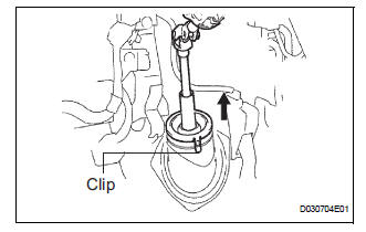
(b) Release the 3 clips and separate the dust cover.
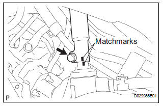
(c) Align the matchmarks on the steering intermediate shaft assembly and steering gear assembly.
(d) Remove the bolt and separate the steering intermediate shaft assembly.
18. REMOVE STEERING COLUMN ASSEMBLY
(a) Disconnect the connectors and wire harness clamps.
(b) Remove the 3 bolts and steering column assembly from the instrument panel reinforcement assembly.
 Steering Column Assembly
COMPONENTS
...
 Disassembly
1. REMOVE STEERING INTERMEDIATE SHAFT ASSEMBLY
(a) Align the matchmarks on the steering intermediate
shaft assembly and main shaft.
(b) Remove the bolt and steering intermediate shaft
assemb ...
Other materials:
Brake Warning Light Remains ON
DESCRIPTION
The BRAKE warning light comes on when the brake fluid is insufficient, the
parking brake is applied or the
EBD is defective.
WIRING DIAGRAM
INSPECTION PROCEDURE
HINT:
When releasing the parking brake, move the shift lever into the P position in an
AT vehicle, and choke in
...
ACC Power Source Circuit
DESCRIPTION
This circuit supplies power to the A/C amplifier and the illumination for the
clock.
WIRING DIAGRAM
INSPECTION PROCEDURE
1 INSPECT FUSE (ECU ACC)
(a) Remove the ECU ACC fuse from the engine room relay
block.
(b) Measure the resistance according to the value(s) in the
tab ...
Glossary of tire terminology
Tire related term
Meaning
Cold tire inflation
pressure
Tire pressure when the vehicle has been
parked for three hours or more, or has not
been driven more than 1 mile or 1.5 km under
that condition
Maximum inflation
pressure
The maximum cold i ...
