Toyota Sienna Service Manual: Disassembly
1. REMOVE STEERING INTERMEDIATE SHAFT ASSEMBLY
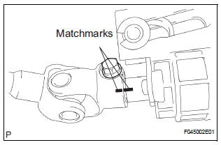
(a) Align the matchmarks on the steering intermediate shaft assembly and main shaft.
(b) Remove the bolt and steering intermediate shaft assembly.
2. REMOVE KEY CYLINDER LIGHT ASSEMBLY (w/o Engine Immobiliser System)
3. REMOVE TRANSPONDER KEY AMPLIFIER (w/ Engine Immobiliser System)
(a) Widen the claw hanging onto the upper bracket by approx. 1.0 mm (0.039 in.) using a screwdriver.
(b) Pull the transponder key amplifier toward the rear of the vehicle with the claw open.
NOTICE: Take care not to use excessive force to prevent the case from being damaged.
4. REMOVE STEERING COLUMN BRACKET ASSEMBLY UPPER
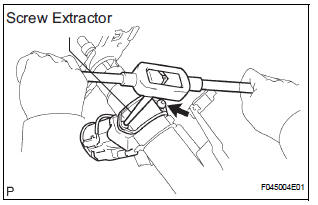
(a) Using a centering punch, mark the center of the 2 tapered-head bolts.
(b) Using a 3 to 4 mm (0.12 to 0.16 in.) drill, drill a hole into the heads of the 2 bolts.
(c) Using a screw extractor, remove the 2 bolts and steering column upper w/ switch bracket assembly.
5. REMOVE IGNITION SWITCH LOCK CYLINDER ASSEMBLY
(a) Place the ignition switch lock cylinder assembly in the ACC position.
(b) Push down the stop pin with a screwdriver, and pull out the cylinder assembly.
6. REMOVE UN-LOCK WARNING SWITCH ASSEMBLY
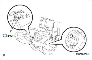
(a) Disconnect the un-lock warning switch assembly connector from the ignition or starter switch assembly.
(b) Remove the un-lock warning switch assembly by pushing up the center part and releasing the 2 claws.
(c) Disengage the secondary locking device.
(d) Using a screwdriver, disengage the locking lug of terminals 1 and 2, and pull the terminals out from the rear side of the un-lock warning switch assembly.
7. REMOVE KEY INTER LOCK SOLENOID
(a) Remove the 2 screws and solenoid from the steering column bracket assembly.
8. REMOVE IGNITION OR STARTER SWITCH ASSEMBLY
(a) Remove the 2 screws and ignition or starter switch assembly from the steering column bracket assembly UPR.
 Removal
1. PRECAUTION
HINT:
See page RS-1
2. DISCONNECT BATTERY NEGATIVE TERMINAL
Wait for 90 seconds after disconnecting the battery
terminal to prevent the airbag working.
3. PLACE FRONT WHEELS FACING ...
 Reassembly
1. INSTALL IGNITION OR STARTER SWITCH
ASSEMBLY
(a) Install the ignition or starter switch assembly to the
steering column bracket assembly UPR with the 2
screws.
2. INSTALL KEY INTER LOCK SOLENOI ...
Other materials:
Precaution
1. Before operating the power rear no. 2 seat with
stowing function, make sure that there is nothing in
the path of the seat.
CAUTION:
If someone or something is caught between the seat
and other parts, injury or damage may result.
If the system detects that the folding motor is locke ...
Vehicle Speed Signal Error (Test Mode DTC)
DTC C2191/91 Vehicle Speed Signal Error (Test Mode DTC)
DESCRIPTION
The tire pressure warning ECU receives a speed signal from the combination
meter. This DTC is stored
upon entering test mode, and cleared when a vehicle speed signal of 12 mph (20
km/h) is detected for 3
seconds or more. Thi ...
Basic inspection
When a malfunction is not confirmed by the DTC check,
troubleshooting should be carried out in all circuits
considered to be possible causes of the problem. In many
cases, by carrying out the basic engine check shown in the
following flowchart, the location of the problem can be found
quickly a ...
