Toyota Sienna Service Manual: Removal
1. DISCHARGE REFRIGERANT FROM REFRIGERATION SYSTEM
SST 07110-58060 (07117-58080, 07117-58090, 07117-78050, 07117-88060, 07117-88070, 07117-88080)
HINT: See page AC-172.
2. REMOVE REAR DOOR SCUFF PLATE RH (See page IR-7)
3. REMOVE BACK DOOR SCUFF PLATE (See page IR- 8)
4. REMOVE QUARTER TRIM PANEL ASSEMBLY FRONT RH (See page IR-9)
5. REMOVE ROOF HEADLINING GARNISH REAR (See page IR-9)
6. REMOVE RR WINDOW SIDE GARNISH ASSEMBLY NO.2 RH (See page IR-9)
7. REMOVE AIR DUCT ASSEMBLY
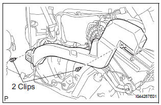
(a) Remove the 2 clips and the air duct assembly from the air conditioning blower assembly.
8. REMOVE COVER SUB-ASSEMBLY
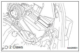
(a) Disengage the 2 claw fittings and remove the cover sub-assembly.
9. REMOVE AIR DUCT ASSEMBLY
(a) Remove the air duct assembly.
10. DISCONNECT HEATER HOSE
(a) Release the claw fittings and release the heater hose clamp.
(b) Using pliers, grip the claws of the 2 clips and slide the clip to disconnect the 2 heater hoses.
11. DISCONNECT AIR CONDITIONING TUBE AND ACCESSORY ASSEMBLY
(a) Remove the 2 bolts and disconnect the air conditioning tube & accessory assembly.
12. REMOVE AIR CONDITIONING BLOWER ASSEMBLY
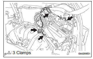
(a) Disconnect the 4 connectors, release the 3 clamps and separate the wire harness.
(b) Remove the 3 bolts and the air conditioning blower assembly.
 Blower unit (for rear air conditioning system)
COMPONENTS
...
 Disassembly
1. REMOVE COOLER THERMISTOR NO.1 (for Automatic Air Conditioning System)
(a) Disengage the 2 claw fittings and the clamp and
remove the cooler thermistor No. 1.
2. REMOVE COOLING UNIT MOTOR SUB ...
Other materials:
Inspection
1. INSPECT BRAKE VACUUM CHECK VALVE ASSEMBLY
(a) Check the vacuum check valve.
(1) Slide the clip and disconnect the vacuum hose.
(2) Remove the vacuum check valve.
(3) Check that there is ventilation from the booster
to the engine, and no ventilation from the
engine to the booster.
...
Front Airbag Sensor RH Circuit Malfunction
DTC B1148/36 Front Airbag Sensor RH Circuit Malfunction
DESCRIPTION
The front airbag sensor RH circuit consists of the center airbag sensor
assembly and front airbag sensor
RH. If the center airbag sensor assembly receives signals from the front airbag
sensor RH, it judges
whether or not the ...
Diagnosis system
1. CHECK DLC3
The ECU uses ISO 15765-4 for communication.
The terminal arrangement of the DLC3 complies
with SAE J1962 and matches the ISO 15765-4
format.
NOTICE:
*: Before measuring the resistance, leave the
vehicle as is for at least 1 minute and do not
operate the igniti ...
