Toyota Sienna Service Manual: Disassembly
1. REMOVE COOLER THERMISTOR NO.1 (for Automatic Air Conditioning System)
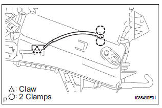
(a) Disengage the 2 claw fittings and the clamp and remove the cooler thermistor No. 1.
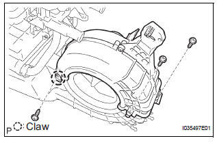
2. REMOVE COOLING UNIT MOTOR SUB-ASSEMBLY WITH FAN
(a) Remove the 3 screws and the cooling unit motor sub-assembly w/ fan.
3. REMOVE BLOWER RESISTOR TRANSISTOR ASSEMBLY
(a) Remove the 2 screws and the blower resistor transistor assembly.
4. REMOVE HEATER RADIATOR UNIT SUB-ASSEMBLY
(a) Disengage the claw fitting and remove the 3 screws and blower case.
(b) Remove the 2 screws and the 2 clamps.
(c) Remove the 3 screws and the heater water valve assembly.
(d) Remove the 2 O-rings from the heater water valve assembly.
(e) Remove the heater radiator unit sub-assembly from the air conditioning blower assembly.
 Removal
1. DISCHARGE REFRIGERANT FROM
REFRIGERATION SYSTEM
SST 07110-58060 (07117-58080, 07117-58090,
07117-78050, 07117-88060, 07117-88070,
07117-88080)
HINT:
See page AC-172.
2. REMOVE REAR DOOR SCUF ...
 Reassembly
1. INSTALL HEATER RADIATOR UNIT SUB-ASSEMBLY
(a) Install the heater radiator unit sub-assembly to the
air conditioning blower assembly.
(b) Install the 2 O-rings to the heater water valve
as ...
Other materials:
Inspection
1. INSPECT TIRE PRESSURE WARNING RESET SWITCH
(a) Remove the tire pressure warning reset switch.
(b) Measure the resistance between terminals 1 and 2
of the tire pressure warning reset switch when the
tire pressure warning switch is ON and OFF.
Standard resistance
If the result is not as ...
Open in Front Pretensioner Squib RH Circuit
DTC B0131/64 Open in Front Pretensioner Squib RH Circuit
DESCRIPTION
The front pretensioner squib RH circuit consists of the center airbag sensor
assembly and the front seat
outer belt assembly RH.
This circuit instructs the SRS to deploy when deployment conditions are met.
DTC B0131/64 i ...
On-vehicle inspection
NOTICE:
In this section, the terms "cold" and "hot" refer to the
temperature of the coils. "Cold" means approximately -
10ÂḞC (14ÂḞF) to 50ÂḞC (122ÂḞF). "Hot" means approximately
50ÂḞC (122ÂḞF) to 100ÂḞC (212ÂḞF).
1. INSPECT IGNITION C ...
