Toyota Sienna Service Manual: Removal
1. REMOVE FRONT WIPER ARM HEAD CAP
- Using a small screwdriver, remove the 2 front wiper arm covers.
HINT: Tape up the screwdriver tip before use.
2. REMOVE FR WIPER ARM RH
- Operate the wiper, and stop the windshield wiper motor assembly to the automatic stop position.
- Remove the nut and the FR wiper arm RH.
3. REMOVE FR WIPER ARM LH
- Remove the nut and the FR wiper arm LH.
4. REMOVE COWL TOP VENTILATOR LOUVER SUBASSEMBLY
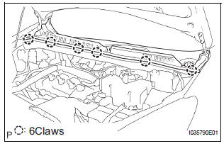
- Remove the 6 claws and the cowl top ventilator louver sub-assembly.
5. REMOVE WINDSHIELD WIPER MOTOR AND LINK ASSEMBLY
- Disconnect the connector.
- Remove the 4 bolts and wiper motor & link assembly.
6. REMOVE WINDSHIELD WIPER MOTOR ASSEMBLY
- Using a screwdriver, disengage the meshing of rod at the crank arm pivot of the windshield wiper motor assembly.
- Remove the 3 bolts and windshield wiper motor assembly from the windshield wiper link assembly.
HINT: Turning the crank arm by hand prior to the operation will be able to remove the wiper motor easier.
 Front wiper motor
COMPONENTS
...
 Inspection
1. INSPECT WINDSHIELD WIPER MOTOR ASSEMBLY
LO Operation Check
Connect the battery (+) to the terminal 1 (+1) of
the connector, the battery (-) to the terminal 5
(E) of th ...
Other materials:
SRS Warning Light Remains ON
DESCRIPTION
The SRS warning light is located on the combination meter assembly.
When the SRS is normal, the SRS warning light comes on for approximately 6
seconds after the ignition
switch is turned from the LOCK position to ON position, and then goes off
automatically.
If there is a mal ...
Adjustment
HINT:
On the RH side, use the same procedures as on the LH side.
1. INSPECT SLIDE DOOR PANEL SUB-ASSEMBLY LH
Check that the clearance is within the standard
range.
Standard
2. ADJUST SLIDE DOOR PANEL SUB-ASSEMBLY LH
Using the SST, horizontally and vertically adjust the
do ...
Air Outlet Damper Position Sensor Circuit
DESCRIPTION
This sensor detects the position of the air outlet control servo motor and
sends the appropriate signals to
the A/C amplifier. The position sensor is built in the air outlet control servo
motor. The position sensor's
resistance changes as the air outlet control servo motor arm ...
