Toyota Sienna Service Manual: Room Temperature Sensor Circuit
DESCRIPTION
This sensor detects the cabin temperature that is used as the basis for
temperature control and sends a
signal to the A/C amplifier. 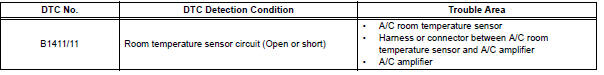
WIRING DIAGRAM 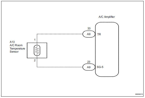
INSPECTION PROCEDURE
1 READ VALUE OF INTELLIGENT TESTER
(a) Connect the intelligent tester to the DLC3.
(b) Turn the ignition switch to the ON position and turn the intelligent tester main switch on.
(c) Select the item below in the DATA LIST, and read the display on the intelligent tester.
DATA LIST / AIR CONDITIONER: 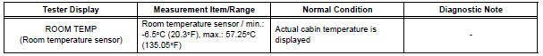
OK: The display is as specified in the normal condition column.
Result 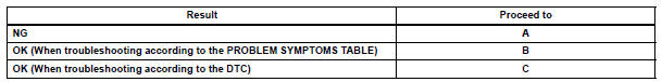

2 INSPECT A/C ROOM TEMPERATURE SENSOR
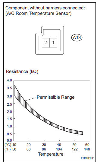
(a) Remove the A/C room temperature sensor.
(b) Measure the resistance according to the value(s) in the table below.
Standard resistance 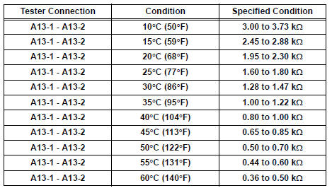
NOTICE:
- Hold the sensor only by its connector. Touching the sensor may change the resistance value.
- When measuring, the sensor temperature must be the same as the room temperature.
HINT: As the temperature increases, the resistance decreases (see the graph).


3 CHECK HARNESS AND CONNECTOR (A/C ROOM TEMPERATURE SENSOR - A/C AMPLIFIER)
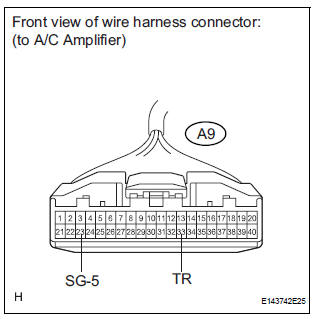
(a) Disconnect the connector from the A/C amplifier.
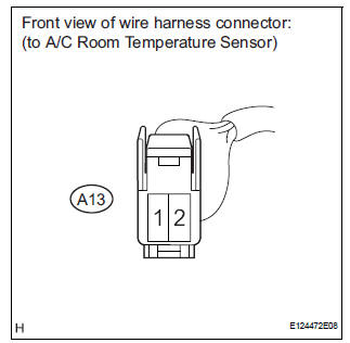
(b) Disconnect the connector from the A/C room temperature sensor.
(c) Measure the resistance according to the value(s) in the table below.
Standard resistance 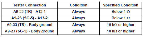

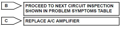
REPLACE A/C AMPLIFIER
 Actuator check
1. ACTUATOR CHECK
(a) After entering the DTC check mode (Sensor Check
Mode), press the R/F switch.
(b) As each damper, motor and relay automatically
operate actuator check at 1-second interval ...
 Ambient temperature sensor circuit
DTC B1412/12 Ambient Temperature Sensor Circuit
DESCRIPTION
The ambient temperature sensor is installed in front of the condenser to
detect the ambient temperature
which is used to control the ai ...
Other materials:
For vehicles equipped with catalytic converter
CAUTION: If a large amount of unburned gasoline or gasoline vapors flow
into the converter, it may cause overheating and create a fire hazard. To
prevent this, observe the following precautions:
(a) Use only unleaded gasoline.
(b) Avoid idling the engine for more than 20 minutes.
(c) ...
Third outside seats
To use
Pull the head restraints up.
To fold
Press the button
Removing the head restraints
Front and second outside seats
Pull the head restraint up while pressing
the lock release button.
Second center* and third center seats
Pull the head restraint up while pressi ...
Ambient temperature sensor circuit
DTC B1412/12 Ambient Temperature Sensor Circuit
DESCRIPTION
The ambient temperature sensor is installed in front of the condenser to
detect the ambient temperature
which is used to control the air conditioner "AUTO" mode. This sensor is
connected to the A/C amplifier
and detects fl ...
