Toyota Sienna Service Manual: Actuator check
1. ACTUATOR CHECK
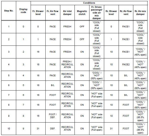
(a) After entering the DTC check mode (Sensor Check Mode), press the R/F switch.
(b) As each damper, motor and relay automatically operate actuator check at 1-second intervals from step No. 1 to No. 10 continuously, check the temperature and air flow visually and by hand.
If the slower display is desired, press the DEF switch and change it to step operation. Each time the DEF switch is pressed, the display changes by 1 step.
HINT:
- Codes are displayed from smaller to larger numbers in order.
- To cancel the check mode, press the OFF switch.
- Room Temperature Sensor Circuit
- Ambient temperature sensor circuit
- Evaporator temperature sensor circuit
- Rear evaporator temperature sensor circuit
- Rear Room Temperature Sensor Circuit
- Solar Sensor Circuit (Passenger Side)
- Compressor Lock Sensor Circuit
- Pressure Sensor Circuit
- Solar Sensor Circuit (Driver Side)
- Air Mix Damper Position Sensor Circuit (Passenger Side)
- Air Inlet Damper Position Sensor Circuit
- Air Outlet Damper Position Sensor Circuit
- Air Mix Damper Position Sensor Circuit (Driver Side)
- Rear Air Mix Damper Position Sensor Circuit
- Rear Air Outlet Damper Position Sensor Circuit
- Air Mix Damper Control Servo Motor Circuit (Passenger Side)
- Air Inlet Damper Control Servo Motor Circuit
- Air Outlet Damper Control Servo Motor Circuit
- Air Mix Damper Control Servo Motor Circuit (Driver Side)
- Rear Air Mix Damper Control Servo Motor Circuit
- Rear Air Outlet Damper Control Servo Motor Circuit
- Compressor Solenoid Circuit
- Multiplex Communication Circuit
- Blower Motor Circuit
- Air Conditioning Compressor Magnetic Clutch Circuit
- Rear Air Conditioning Control Panel Circuit
- Rear Air Conditioning Relay Circuit
- Rear Blower Motor Circuit
- IG Power Source Circuit
- ACC Power Source Circuit
- Back-up Power Source Circuit
 Diagnostic trouble code chart
If a trouble code is displayed during the DTCs check (sensor
check), check the circuit listed for the code in the table below
(Proceed to the page given for that circuit).
AIR CONDITIONING SYSTEM
...
 Room Temperature Sensor Circuit
DESCRIPTION
This sensor detects the cabin temperature that is used as the basis for
temperature control and sends a
signal to the A/C amplifier.
WIRING DIAGRAM
INSPECTION PROCEDURE
1 READ VAL ...
Other materials:
Installation
1. INSTALL TIRE PRESSURE WARNING RECEIVER ASSEMBLY
(a) Connect the connector.
(b) Install the tire pressure warning receiver assembly
with the bolt.
Torque: 5.0 N*m (51 kgf*cm, 44 in.*lbf)
2. INSTALL ROOF HEADLINING ASSEMBLY
HINT:
Refer to the instructions for INSTALLATION of the ROOF ...
Reassembly
1. INSTALL NO. 2 SEAT LEG SUB-ASSEMBLY
Install the No. 2 seat leg sub-assembly with the 3
bolts and 2 nuts.
Torque: 19 N*m (194 kgf*cm, 14 ft.*lbf)
NOTICE:
Tighten the bolts and nuts in the order shown in
the illustration.
Install the 3 clamps.
2. INSTALL NO. 2 SEA ...
Removal
1. Disconnect cable from negative battery
terminal
2. REMOVE HEATED OXYGEN SENSOR (for Bank 1
Sensor 2) (See page EC-32)
3. REMOVE TAIL EXHAUST PIPE ASSEMBLY
(a) Remove the 2 bolts.
(b) Disconnect the 3 exhaust pipe supports and remove
the tail exhaust pipe assembly.
(c) Remove the gas ...
