Toyota Sienna Service Manual: Security Indicator Light Circuit
DESCRIPTION
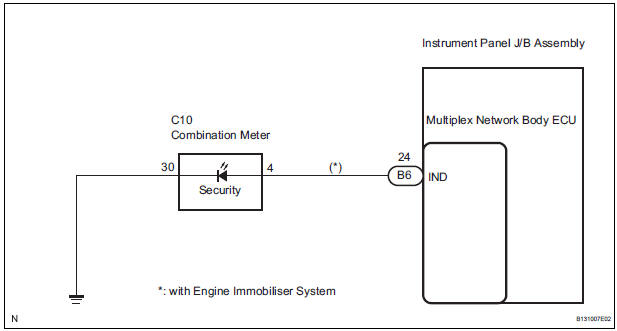
Even when the theft deterrent system is in the disarmed state, the security indicator blinks due to a signal output from the immobiliser system. The security indicator blinks continuously due to a continuous signal received from the immobiliser system while in the armed state.
The multiplex network body ECU causes the security indicator to light up or blink only during the arming preparation state and alarm sounding states.
WIRING DIAGRAM
INSPECTION PROCEDURE
1 INSPECT COMBINATION METER ASSEMBLY
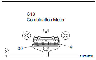
- Remove the combination meter assembly.
- Apply battery voltage between the terminals of the indicator, and check the lighting condition of the security indicator.
Standard
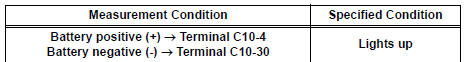
NOTICE:
- If the positive (+) lead and the negative (-) lead are incorrectly connected, the security indicator will not light up.
- Voltage of more than 12 V will damage the security indicator
- If the voltage is too low, the security indicator will not light up.
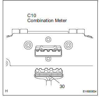
2 CHECK HARNESS AND CONNECTOR (COMBINATION METER ASSEMBLY - MULTIPLEX NETWORK BODY ECU)
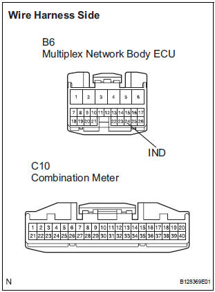
- Disconnect the B6 ECU connector.
- Disconnect the C10 meter connector.
- Measure the resistance according to the value(s) in the table below.
Standard resistance
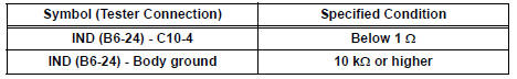
3 CHECK HARNESS AND CONNECTOR (COMBINATION METER - BODY GROUND)
- Measure the resistance according to the value(s) in the table below.
Standard resistance

REPLACE MULTIPLEX NETWORK BODY ECU
 Ignition Switch Circuit
DESCRIPTION
When the ignition switch is turned to the ON position, battery positive
voltage is applied to terminal IG of
the ECU. When battery positive voltage is applied to terminal IG of the ECU ...
 ECU Power Source Circuit
DESCRIPTION
This circuit provides power to operate the theft deterrent (warning) ECU.
WIRING DIAGRAM
INSPECTION PROCEDURE
1 INSPECT FUSE (ECU-B)
Remove the ECU-B fuse from the engine room ...
Other materials:
Data list / active test
1. DATA LIST
HINT:
Using the DATA LIST displayed on the intelligent tester,
you can read the value of the switch, sensor, actuator,
etc. without parts removal. Reading the DATA LIST as
the first step of troubleshooting is one way to shorten the
labor time.
Connect the intelligent tester to ...
Throttle / Pedal Position Sensor / Switch "A"
HINT:
These DTCs relate to the Throttle Position (TP) sensor.
DESCRIPTION
HINT:
This ETC (Electrical Throttle Control System) does not use a throttle cable.
The Throttle Position (TP) sensor is mounted on the throttle body, and detects
the opening angle of the
throttle valve. This sens ...
For vehicles equipped with catalytic converter
CAUTION: If a large amount of unburned gasoline or gasoline vapors flow
into the converter, it may cause overheating and create a fire hazard. To
prevent this, observe the following precautions:
(a) Use only unleaded gasoline.
(b) Avoid idling the engine for more than 20 minutes.
(c) ...
