Toyota Sienna Service Manual: Short in Side Squib RH Circuit
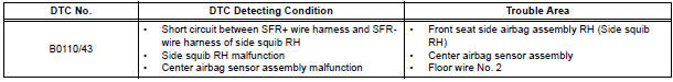
DTC B0110/43 Short in Side Squib RH Circuit
DESCRIPTION
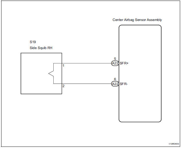
The side squib RH circuit consists of the center airbag sensor assembly and the front seat side airbag assembly RH.
The circuit instructs the SRS to deploy when deployment conditions are met.
DTC B0110/43 is recorded when a short circuit is detected in the side squib RH circuit.
WIRING DIAGRAM
INSPECTION PROCEDURE
HINT:
- Perform the simulation method by selecting the "check mode" (signal check) with the intelligent tester
- After selecting the "check mode" (signal check), perform the simulation method by wiggling each connector of the airbag system or driving the vehicle on a city or rough road
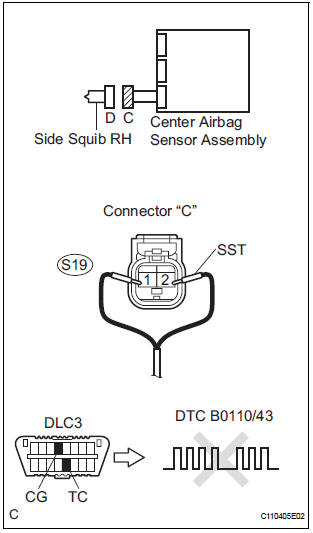
1 CHECK FRONT SEAT SIDE AIRBAG ASSEMBLY RH (SIDE SQUIB RH)
- Turn the ignition switch to the LOCK position.
- Disconnect the negative (-) terminal cable from the battery, and wait for at least 90 seconds.
- Disconnect the connectors from the front seat side airbag assembly RH.
- Connect the black wire side of SST (resistance 2.1 Ω) to the floor wire No. 2.
CAUTION: Never connect a tester to the front seat side airbag assembly RH (side squib RH) for measurement, as this may lead to a serious injury due to airbag deployment.
NOTICE: Do not forcibly insert the SST into the terminals of the connector when connecting.
Insert the SST straight into the terminals of the connector.
SST 09843-18060
- Connect the negative (-) terminal cable to the battery, and wait for at least 2 seconds.
- Turn the ignition switch to the ON position, and wait for at least 60 seconds.
- Clear the DTCs stored in memory.
- Turn the ignition switch to the LOCK position.
- Turn the ignition switch to the ON position, and wait for at least 60 seconds.
- Check the DTCs.
OK: DTC B0110/43 is not output.
HINT: Codes other than DTC B0110/43 may be output at this time, but they are not related to this check.
REPLACE FRONT SEAT ASSEMBLY RH
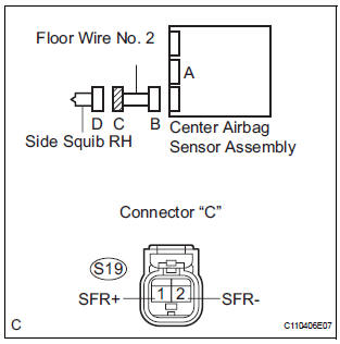
2 CHECK FLOOR WIRE NO.2 (SIDE SQUIB RH CIRCUIT)
- Turn the ignition switch to the LOCK position.
- Disconnect the negative (-) terminal cable from the battery, and wait for at least 90 seconds.
- Disconnect the SST (resistance 2.1 Ω) from the floor wire No. 2.
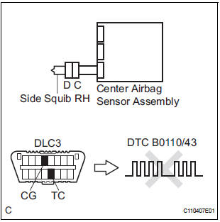
- Disconnect the connector from the center airbag sensor assembly.
- Release the activation prevention mechanism built into connector "B".
- Measure the resistance according to the value(s) in the table below.
Standard resistance
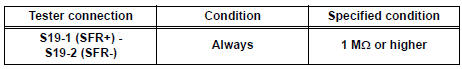
3 CHECK CENTER AIRBAG SENSOR ASSEMBLY
- Connect the connectors to the front seat side airbag assembly RH and the center airbag sensor assembly.
- Connect the negative (-) terminal cable to the battery, and wait for at least 2 seconds.
- Turn the ignition switch to the ON position, and wait for at least 60 seconds.
- Clear the DTCs stored in memory.
- Turn the ignition switch to the LOCK position.
- Turn the ignition switch to the ON position, and wait for at least 60 seconds.
- Check the DTCs.
OK: DTC B0110/43 is not output.
HINT: Codes other than code B0110/43 may be output at this time, but they are not related to this check.
USE SIMULATION METHOD TO CHECK
 Short to B+ in Front Passenger Side Squib Circuit
DTC B0108/52 Short to B+ in Front Passenger Side Squib Circuit
DESCRIPTION
The front passenger side squib circuit consists of the center airbag sensor
assembly and the front
passenger airbag asse ...
 Open in Side Squib RH Circuit
DTC B0111/44 Open in Side Squib RH Circuit
DESCRIPTION
The side squib RH circuit consists of the center airbag sensor assembly and
the front seat side airbag
assembly RH.
The circuit instructs ...
Other materials:
Speedometer Malfunction
DESCRIPTION
Factors that affect the indicated vehicle speed include tire size, tire
inflation, and tire wear. The speed indicated on the speedometer has an
allowable margin of error. This can be tested using a speedometer tester
(calibrated chassis dynamometer). For details about testing and ...
Air Mix Damper Position Sensor Circuit (Driver Side)
DESCRIPTION
This sensor detects the position of the air mix control servo motor (air
outlet damper) and sends the
appropriate signals to the A/C amplifier. The position sensor is built in the
air mix control servo motor. The
position sensor resistance changes as the air mix control servo ...
Radio Broadcast cannot be Received or Poor Reception
INSPECTION PROCEDURE
1 CHECK RADIO AND NAVIGATION ASSEMBLY
Check the radio's automatic station search function.
Check the radio's automatic station search function
by activating it.
OK:
The radio's automatic station search function
works properly.
2 INSPECT RADIO AND NAVIGATION AS ...
