Toyota Sienna Service Manual: Speaker Circuit
DESCRIPTION
The sound signal that has been amplified by the stereo component amplifier is sent to the speakers from the stereo component amplifier through this circuit.
If there is a short in this circuit, the stereo component amplifier detects it and stops output to the speakers.
Thus sound cannot be heard from the speakers even if there is no malfunction in the stereo component amplifier or speakers.
When a short is detected in the speaker circuit, no sound can be heard from the speakers.
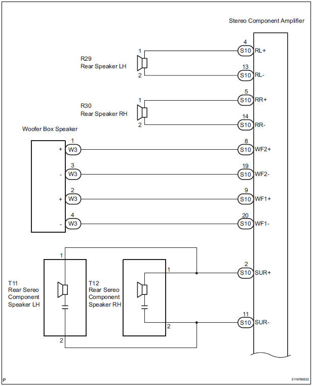
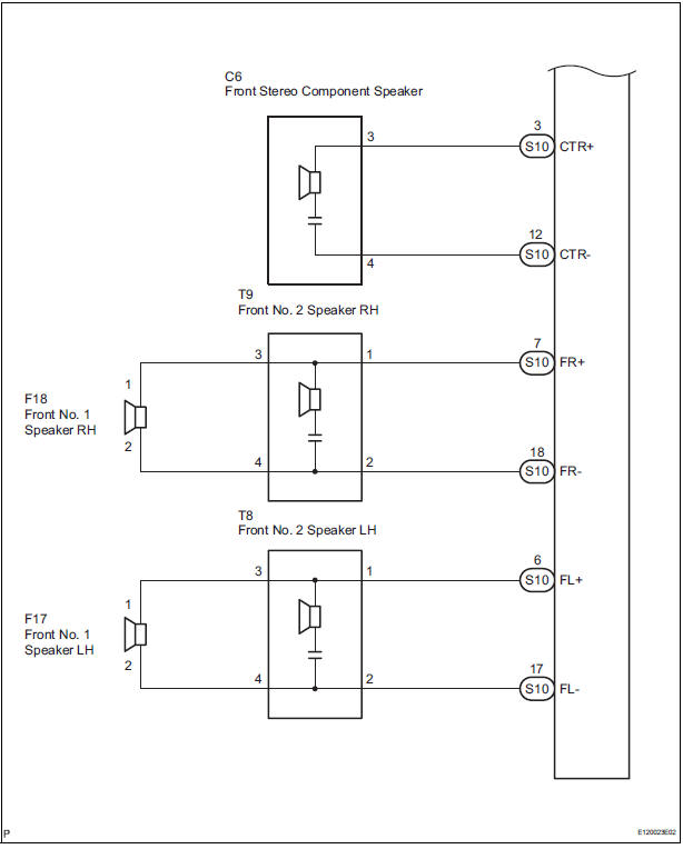
WIRING DIAGRAM
INSPECTION PROCEDURE
1 CHECK HARNESS AND CONNECTOR
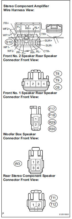
- Disconnect the connectors shown in the illustration on the left from the stereo component amplifier and speakers.
- Measure the resistance between the front No. 2
speakers and the stereo component amplifier to check
for an open circuit in the wire harness.
Standard resistance: Below 1 Ω
- Measure the resistance between rear speakers and the
stereo component amplifier to check for an open circuit
in the wire harness.
Standard resistance: Below 1 Ω
- Measure the resistance between the front stereo
component speaker and the stereo component amplifier
to check for an open circuit in the wire harness.
Standard resistance: Below 1 Ω
- Measure the resistance between the woofer box speaker
and the stereo component amplifier to check for an open
circuit in the wire harness.
Standard resistance: Below 1 Ω
- Measure the resistance between the front No. 1 speaker
and the front No. 2 speaker to check for an open circuit
in the wire harness.
Standard resistance: Below 1 Ω
- Measure the resistance between the rear stereo
component speaker and the stereo component amplifier
to check for an open circuit in the wire harness.
Standard resistance: Below 1 Ω
- Measure the resistance between each speaker and body
ground to check for a short circuit in the wire harness.
Standard resistance: 10 kΩ or higher
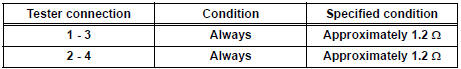
2 INSPECT WOOFER BOX SPEAKER
- Resistance check.
- Measure the resistance according to the value(s) in the table below.
NOTICE: The speaker should not be removed for checking.
Standard resistance
INSPECT FRONT NO. 1 SPEAKER
- Resistance check.
- Measure the resistance between the terminals of the speaker.
Standard resistance: 4 to 6 Ω
4 INSPECT FRONT NO. 2 SPEAKER
- Check that the malfunction disappears when another speaker in good condition is installed.
OK: Malfunction disappears.
HINT:
- Connect all the connectors to the front No. 2 speakers.
- When there is a possibility that either right or left front speaker is defective, inspect by interchanging the right one with the left one.
5 INSPECT REAR SPEAKER
- Resistance check.
- Measure the resistance between the terminals of the speaker.
Standard resistance: Approximately 2.6 Ω
6 INSPECT FRONT STEREO COMPONENT SPEAKER
- Resistance check.
- Measure the resistance between the terminals of the speaker.
Standard resistance: 1.2 to 2.2 Ω
7 INSPECT REAR STEREO COMPONENT SPEAKER
- Check that the malfunction disappears when another speaker in good condition is installed.
OK: Malfunction disappears.
HINT:
- Connect all the connectors to the rear stereo component speakers.
- When there is a possibility that either right or left front speaker is defective, inspect by interchanging the right one with the left one.
PROCEED TO NEXT CIRCUIT INSPECTION SHOWN IN PROBLEM SYMPTOMS TABLE
 Parking Brake Switch Circuit
DESCRIPTION
This circuit is from the parking brake switch to the radio and navigation
assembly.
WIRING DIAGRAM
INSPECTION PROCEDURE
1 CHECK BRAKE WARNING LIGHT
Check that the brake warni ...
 Sound Signal Circuit between Radio and Navigation Assembly and
Television Display Assembly
Sound Signal Circuit between Radio and Navigation Assembly and
Television Display Assembly
DESCRIPTION
The television display assembly sends an RSE sound signal to the radio and
navigation assembly through
this circuit. The sound signal that has been sent is amplified by the stereo
co ...
Other materials:
Stereo Component Amplifier Power Source Circuit
DESCRIPTION
This circuit provides power to the stereo component amplifier.
WIRING DIAGRAM
INSPECTION PROCEDURE
1 INSPECT STEREO COMPONENT AMPLIFIER
Disconnect the stereo component amplifier connectors.
Measure the resistance according to the values in the
table below.
Standard ...
Wiper and washer system
PRECAUTION
1. PRECAUTION OF WASHER NOZZLE ADJUSTMENT
Do not clean or adjust the washer nozzle with a
safety pin, etc. because;
the washer nozzle tip is made of resin and could
be damaged.
adjustment is not necessary because the
washer nozzle is a spray type.
...
Repair
1. INTRODUCTION
(a) This section introduces ways to determine whether
the run-flat tire is repairable or not. Repair must be
performed by following the appropriate procedures.
If a flat tire occurs, it is possible to drive a maximum
of 160 km (100 miles) at a speed below 90 km/h (55
mph) due ...
