Toyota Sienna Service Manual: Stereo Component Amplifier Communication Error
INSPECTION PROCEDURE
1 IDENTIFY THE COMPONENT SHOWN BY THE SUB-CODE
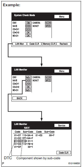
- Enter the diagnostic mode.
- Press the "LAN Mon" switch to change to "LAN Monitor" mode.
- Identify the component shown by the sub-code.
HINT:
- "110 (multi-display)" is the component shown by the sub-code in the example shown in the illustration.
- The sub-code will be indicated by its physical address.
- For the component list, refer to "DIAGNOSIS DISPLAY DETAILED DESCRIPTION".
2 CHECK POWER SOURCE CIRCUIT OF COMPONENT SHOWN BY SUB-CODE
- Inspect the power source circuit of the component shown
by the sub-code.
If the power source circuit is operating normally, proceed to the next step.
Component Table:

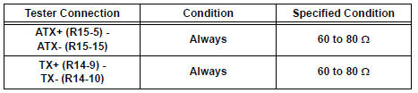
3 CHECK RADIO AND NAVIGATION ASSEMBLY
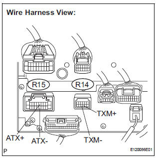
- Disconnect the radio and navigation assembly connectors.
- Measure the resistance according to the value(s) in the table below.
Standard resistance
4 CHECK HARNESS AND CONNECTOR (STEREO COMPONENT AMPLIFIER - COMPONENT SHOWN BY SUB-CODE)
HINT:
- Start the check from the circuit that is near the component shown by the sub-code first.
- For details of the connectors, refer to "TERMINALS OF ECU".
- Referring to the AVC-LAN wiring diagram below, check the AVC-LAN circuit between the stereo component amplifier and the component shown by the sub-code.
- Disconnect all connectors between the stereo component amplifier and the component shown by sub-code.
- Check for an open or short in the AVC-LAN circuit between the stereo component amplifier and the component shown by the sub-code.
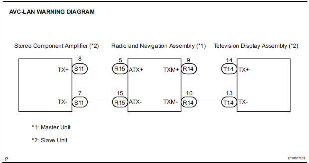
OK: There is no open or short circuit.
5 REPLACE COMPONENT SHOWN BY SUB-CODE
- Replace the component shown by the sub-code with a normal one and check if the same problem occurs again.
OK: Same problem does not occur
END
 Microphone Circuit between Microphone and Radio and Navigation
Assembly
Microphone Circuit between Microphone and Radio and Navigation
Assembly
DESCRIPTION
This circuit sends a microphone signal from the microphone to the radio and
navigation assembly.
It also supplies power from the radio and navigation assembly to the microphone.
WIR ...
 Radio and Navigation Assembly Communication Error
INSPECTION PROCEDURE
1 IDENTIFY THE COMPONENT SHOWN BY THE SUB-CODE
Enter the diagnostic mode.
Press the "LAN Mon" switch to change to "LAN Monitor"
mode.
&nbs ...
Other materials:
Inspection
1. INSPECT FRONT SEAT INNER BELT ASSEMBLY RH
Release the seat belt (Buckle switch is ON).
Check the resistance between the terminals.
Standard
If the result is not as specified, replace the inner belt
assembly.
Inspect the buckle switch.
Fasten ...
Short in Driver Side Squib Circuit
DTC B0100/13 Short in Driver Side Squib Circuit
DESCRIPTION
The driver side squib circuit consists of the center airbag sensor assembly,
the spiral cable and the
steering pad. The circuit instructs the SRS to deploy when deployment conditions
are met. DTC B0100/13
is recorded when a short ci ...
MIL Circuit
DESCRIPTION
The MIL (Malfunction Indicator Lamp) is used to indicate vehicle malfunctions
detected by the ECM.
When the ignition switch is turned to the ON position, power is supplied to the
MIL circuit, and the ECM
provides the circuit ground which illuminates the MIL.
The MIL operation ...
