Toyota Sienna Service Manual: Microphone Circuit between Microphone and Radio and Navigation Assembly
DESCRIPTION
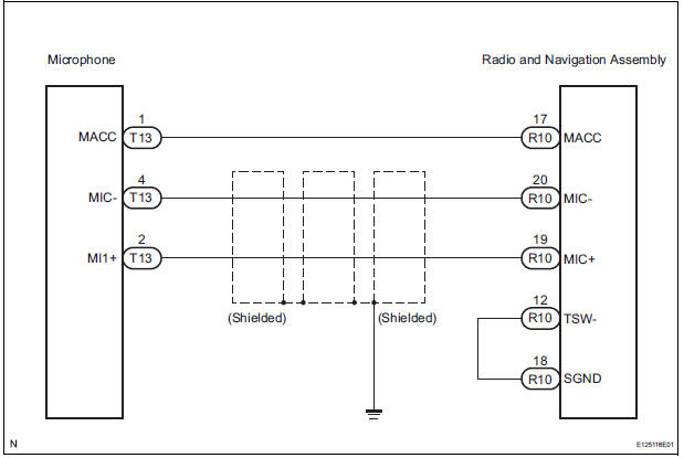
This circuit sends a microphone signal from the microphone to the radio and navigation assembly.
It also supplies power from the radio and navigation assembly to the microphone.
WIRING DIAGRAM
INSPECTION PROCEDURE
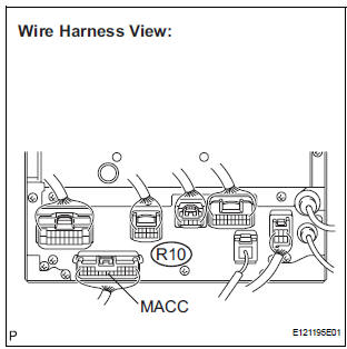
1 INSPECT RADIO AND NAVIGATION ASSEMBLY
- Measure the voltage according to the value(s) in the table below.
Standard voltage
2 CHECK HARNESS AND CONNECTOR
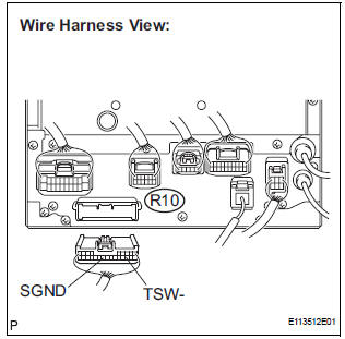
- Disconnect the radio and navigation assembly connector R10.
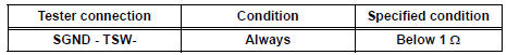
- Measure the resistance according to the value(s) in the table below.
Standard resistance
3 CHECK HARNESS AND CONNECTOR (MICROPHONE - RADIO AND NAVIGATION ASSEMBLY)

- Disconnect the microphone connector T13 and radio and navigation assembly connector R10.
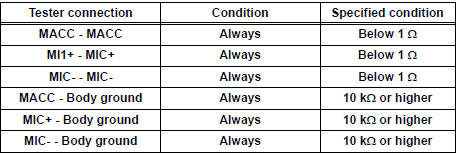
- Measure the resistance according to the value(s) in the table below.
Standard resistance
PROCEED TO NEXT CIRCUIT INSPECTION SHOWN IN PROBLEM SYMPTOMS TABLE
 Display Signal Circuit between Television Display Assembly and Radio
and Navigation Assembly
Display Signal Circuit between Television Display Assembly and Radio
and Navigation Assembly
DESCRIPTION
This circuit sends a DVD image signal from the television display assembly to
the radio and navigation
assembly.
WIRING DIAGRAM
INSPECTION PROCEDURE
1 CHECK HARNESS AND CONNECTO ...
 Stereo Component Amplifier Communication Error
INSPECTION PROCEDURE
1 IDENTIFY THE COMPONENT SHOWN BY THE SUB-CODE
Enter the diagnostic mode.
Press the "LAN Mon" switch to change to "LAN Monitor"
mode.
&nbs ...
Other materials:
Display Panel does not Open, Tilt or Tilts Improperly
INSPECTION PROCEDURE
1 CHECK RADIO AND NAVIGATION ASSEMBLY
Check for foreign matter or obstructions caught in the
moving parts of the panel.
OK:
No obstruction or foreign matter found.
2 CHECK OPERATION
Check if the navigation and audio systems function
properly.
OK:
Naviga ...
ECM Power Source Circuit
DESCRIPTION
When the ignition switch is turned to the ON position, the battery voltage is
applied to terminal IGSW of
the ECM. The ECM MREL output signal causes a current to flow to the coil,
closing the contacts of the EFI
relay and supplying power to terminal +B of the ECM.
If the igniti ...
On-vehicle inspection
1. INSPECT SIDE AIRBAG SENSOR (VEHICLE NOT
INVOLVED IN COLLISION)
Perform a diagnostic system check.
2. INSPECT SIDE AIRBAG SENSOR (VEHICLE
INVOLVED IN COLLISION AND AIRBAG HAS NOT
DEPLOYED)
Perform a diagnostic system check.
When the center pillar of the vehicle or ...
