Toyota Sienna Service Manual: TC and CG Terminal Circuit
DESCRIPTION
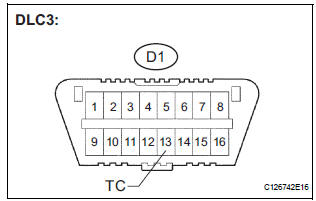
Connecting terminals TC and CG of the DLC3 causes the system to enter the self-diagnostic mode. If a malfunction is present, DTCs will be output.
HINT: When a particular warning light remains blinking, a ground short in the wiring of terminal TC of the DLC3 or an internal ground short in the relevant ECU is suspected.
WIRING DIAGRAM
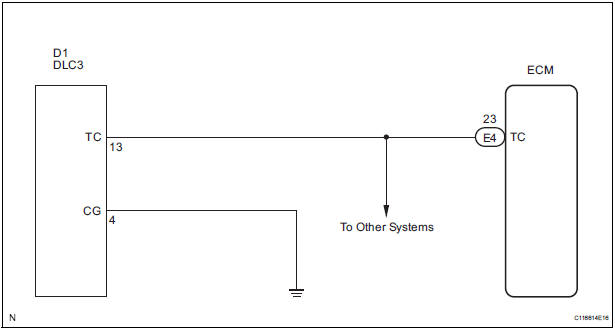
INSPECTION PROCEDURE
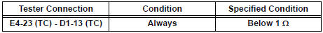
1 CHECK HARNESS AND CONNECTOR (TERMINAL TC of DLC3 - ECM)

- Disconnect the E4 connector from the ECM.
- Measure the resistance according to the value(s) in the table below.
Standard resistance
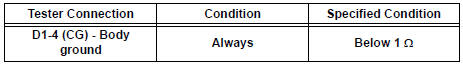
2 CHECK HARNESS AND CONNECTOR (TERMINAL CG of DLC3 - BODY GROUND)
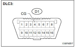
- Measure the resistance according to the value(s) in the table below.
Standard resistance
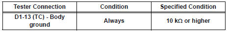
3 CHECK HARNESS AND CONNECTOR (TERMINAL TC of DLC3 - BODY GROUND)
- Measure the resistance according to the value(s) in the table below.
Standard resistance
PROCEED TO NEXT CIRCUIT INSPECTION SHOWN IN PROBLEM SYMPTOMS TABLE
 Cruise Main Indicator Light Circuit
DESCRIPTION
When the cruise control main switch is on, the CRUISE main indicator light
and READY indicator light
come on. This indicates the control condition (presence or absence of a vehicle
i ...
 Cruise control main switch
COMPONENTS
Removal
1. DISCONNECT BATTERY NEGATIVE TERMINAL
2. REMOVE STEERING WHEEL COVER LOWER NO.2
(24)
3. REMOVE STEERING WHEEL COVER LOWER NO.3
(24)
4. REMOVE HORN BUTTON ASSEMBLY
...
Other materials:
CD Abnormal/ Excess Current/ Tray Insertion / Ejection Error
DTC 63-44 CD Abnormal
DTC 63-48 Excess Current
DTC 63-50 Tray Insertion / Ejection Error
DESCRIPTION
DTC No.
DTC Detection Condition
Trouble Area
63-44
Operation error in the CD mechanism
Radio and navigation assembly
63-48
Excess current is pr ...
Disassembly
1. REMOVE FRONT BUMPER ENERGY ABSORBER
2. REMOVE FRONT BUMPER REINFORCEMENT SUBASSEMBLY
Remove the 6 bolts and the front bumper
reinforcement sub-assembly.
3. REMOVE FRONT BUMPER SIDE SUPPORT LH
Remove the screw.
Disengage the 2 clips and remove the front bumper
side suppor ...
Adjustment
1. VEHICLE PREPARATION FOR FOG LIGHT AIMING
Prepare the vehicle:
Ensure there is no damage or deformation to the
body around the fog lights.
Fill the fuel tank.
Make sure that the oil is filled to the specified
level.
Make sure that the coolant is fi ...
