Toyota Sienna Service Manual: Disassembly
1. REMOVE FRONT BUMPER ENERGY ABSORBER
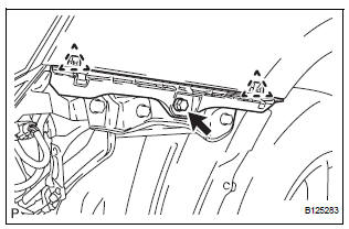
2. REMOVE FRONT BUMPER REINFORCEMENT SUBASSEMBLY
- Remove the 6 bolts and the front bumper reinforcement sub-assembly.
3. REMOVE FRONT BUMPER SIDE SUPPORT LH
- Remove the screw.
- Disengage the 2 clips and remove the front bumper side support LH.
4. REMOVE FRONT BUMPER SIDE SUPPORT RH
HINT: Perform the same procedure as for the LH side.
5. REMOVE NO. 1 ULTRASONIC SENSOR RETAINER (See page PM-19)
6. REMOVE NO. 1 ULTRASONIC SENSOR (LH side) (w/ Clearance Sonar System) (See page PM-19)
7. REMOVE NO. 1 ULTRASONIC SENSOR (RH side) (w/ Clearance Sonar System)
HINT: Perform the same procedure as for the LH side.
8. REMOVE RADIATOR GRILLE
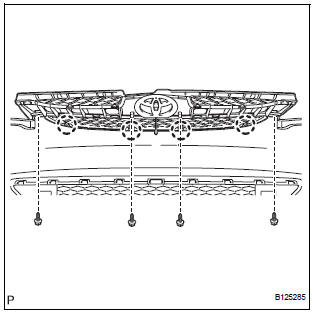
- Remove the 2 bolts and the 2 screws.
- Disengage the 4 claws and remove the radiator grille from the front bumper cover.
9. REMOVE UPPER RADIATOR GRILLE
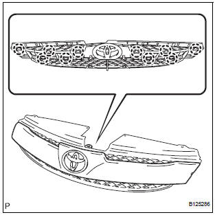
- Disengage the 10 claws and remove the upper radiator grille from the radiator grille.
10. REMOVE FRONT BUMPER EMBLEM
- Disengage the 3 claws and remove the front bumper emblem from the upper radiator grille.
11. REMOVE FRONT BUMPER HOLE COVER LH (w/o Fog Light)
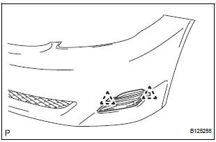
- Disengage the 2 pins and remove the front bumper hole cover LH from the front bumper cover.
12. REMOVE FRONT BUMPER HOLE COVER RH (w/o Fog Light)
HINT: Perform the same procedure as for the LH side.
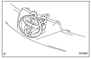
13. REMOVE FOG LIGHT ASSEMBLY LH (w/ Fog Light) (See page LI-82)
14. REMOVE FOG LIGHT ASSEMBLY RH (w/ Fog Light)
HINT: Perform the same procedure as for the LH side.
15. REMOVE LOWER RADIATOR GRILLE
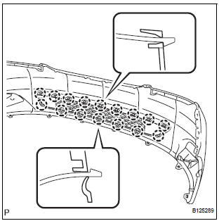
- Disengage the 16 claws and remove the lower radiator grille from the front bumper cover.
 Removal
1. DISCONNECT CABLE FROM NEGATIVE BATTERY
TERMINAL
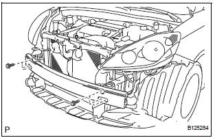
2. REMOVE FRONT BUMPER ASSEMBLY
Remove the 4 screws and separate the fender liner
from the front bumper assembly.
Remove the 8 ...
 Reassembly
1. INSTALL LOWER RADIATOR GRILLE
Engage the 16 claws to install the lower radiator
grille to the front bumper cover.
2. INSTALL FRONT BUMPER HOLE COVER LH (w/o
Fog Light)
Engage ...
Other materials:
Short to GND in Curtain Shield Squib LH Circuit
DTC B1167/85 Short to GND in Curtain Shield Squib LH Circuit
DESCRIPTION
The curtain shield squib LH circuit consists of the center airbag sensor
assembly and the curtain shield
airbag assembly LH.
The circuit instructs the SRS to deploy when deployment conditions are met.
DTC B1167/85 is ...
ABS Warning Light does not Come ON
WIRING DIAGRAM
Refer to ABS Warning Light Remains ON (See page BC-141).
INSPECTION PROCEDURE
1 CHECK ABS WARNING LIGHT
(a) Disconnect the skid control ECU connector.
(b) Turn the ignition switch to the ON position.
(c) Check that the ABS warning light comes on.
OK:
ABS warning light come ...
Pressure Control Solenoid "D" Electrical (Shift
Solenoid Valve SLT)
DESCRIPTION
The linear solenoid valve (SLT) controls the transmission line pressure for
smooth transmission operation
based on signals from the throttle position sensor and the vehicle speed sensor.
The ECM adjusts the
duty cycle of the SLT solenoid valve to control hydraulic line pressure co ...
