Toyota Sienna Service Manual: Air Mix Damper Position Sensor Circuit (Passenger Side)
DESCRIPTION
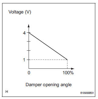
This sensor detects the position of the air mix control servo motor (air mix damper) and sends the appropriate signals to the A/C amplifier. The position sensor is built in the air mix control servo motor. The position sensor's resistance changes as the air mix control servo motor arm moves.
It outputs voltage (5 V) that is input to terminal 1 and terminal 3 via the variable resistor, and then to the A/ C amplifier.
The A/C amplifier determines the arm position based on the input voltage from the position sensor.
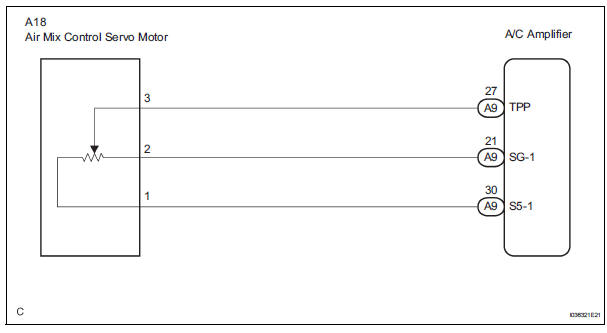
WIRING DIAGRAM
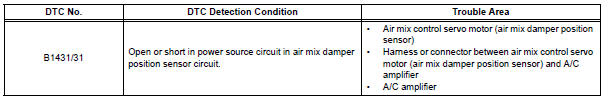
INSPECTION PROCEDURE
1 READ VALUE OF INTELLIGENT TESTER
(a) Connect the intelligent tester to the DLC3.
(b) Turn the ignition switch to the ON position and turn the intelligent tester main switch on.
(c) Select the items below in the DATA LIST, and read the display on the intelligent tester.
DATA LIST / AIR CONDITIONER 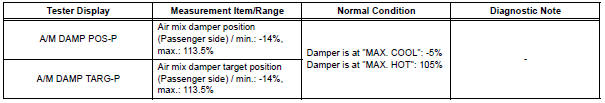
OK: The display is as specified in the normal condition column.
Result 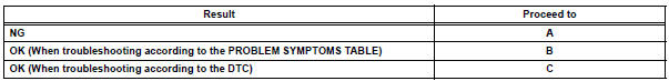

2 INSPECT AIR MIX CONTROL SERVO MOTOR
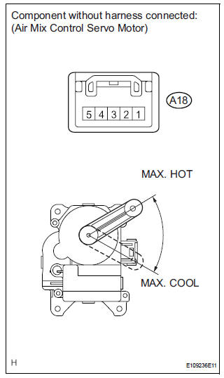
(a) Remove the air mix control servo motor.
(b) Disconnect the connector from the air mix control servo motor.
(c) Measure the resistance according to the value(s) in the table below.
Standard resistance 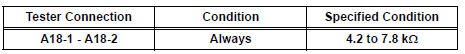
(d) Measure the resistance according to the value(s) in the table below.
Standard resistance 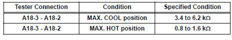
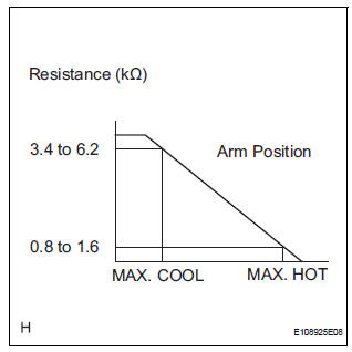
(e) As the air mix control servo motor moves from the cool side to the hot side, the resistance decreases gradually without interruption.

3 CHECK HARNESS AND CONNECTOR (AIR MIX CONTROL SERVO MOTOR - A/C AMPLIFIER)
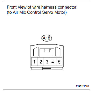
(a) Disconnect the connector from the A/C amplifier.
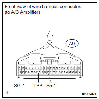
(b) Measure the resistance according to the value(s) in the table below.
Standard resistance 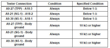

REPLACE A/C AMPLIFIER
 Solar Sensor Circuit (Driver Side)
DESCRIPTION
The solar sensor, which is installed on the upper side of the instrument
panel, detects sunlight and
controls the air conditioning in AUTO mode. The output voltage from the solar
...
 Air Inlet Damper Position Sensor Circuit
DESCRIPTION
This sensor detects the position of the air inlet control servo motor and
sends the appropriate signals to
the A/C amplifier. The position sensor is built in the air inlet control ...
Other materials:
Aluminum wheel precautions
Use only Toyota wheel nuts and wrenches designed for use with
your aluminum wheels.
When rotating, repairing or changing your tires, check that the
wheel nuts are still tight after driving 1000 miles (1600 km).
Be careful not to damage the aluminum wheels when using tire
chains.
Use o ...
Open in Side Squib RH Circuit
DTC B0111/44 Open in Side Squib RH Circuit
DESCRIPTION
The side squib RH circuit consists of the center airbag sensor assembly and
the front seat side airbag
assembly RH.
The circuit instructs the SRS to deploy when deployment conditions are met.
DTC B0111/44 is recorded when an open circ ...
Disassembly
1. SEPARATE REAR DRIVE SHAFT INBOARD JOINT BOOT CLAMP
(a) Using a screwdriver, remove the 2 rear drive shaft
inboard joint boot clamps as shown in the
illustration.
2. SEPARATE REAR DRIVE SHAFT INBOARD JOINT
BOOT
(a) Separate the rear drive shaft inboard joint boot from
the inboard joint ...
