Toyota Sienna Service Manual: Wireless Door Lock Tuner Circuit Malfunction
DTC B1242 Wireless Door Lock Tuner Circuit Malfunction
DESCRIPTION
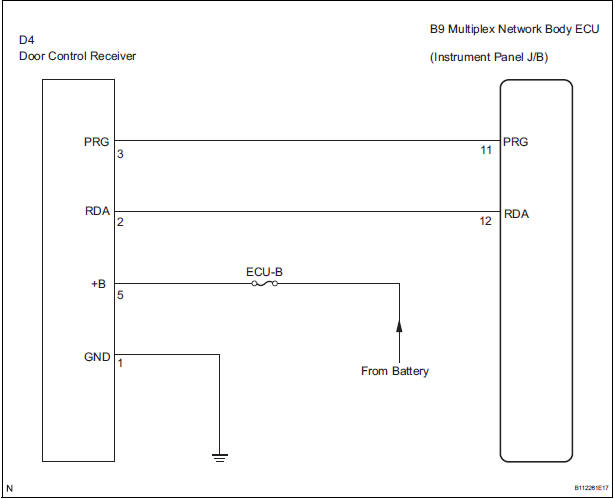
When a RDA signal is not input to the door control receiver within 1 second after the multiplex network body ECU outputs a PRG signal, this DTC is set.
|
DTC No. |
DTC Detection Condition |
Suspected Area |
|
B1242 |
Within 1 second after PRG signal is output from multiplex network body ECU during self-diagnostic mode, corresponding RDA signal is not input |
|
WIRING DIAGRAM
INSPECTION PROCEDURE
1 CHECK HARNESS AND CONNECTOR (DOOR CONTROL RECEIVER - MULTIPLEX NETWORK BODY ECU)
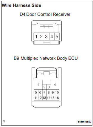
- Disconnect the D4 receiver connector.
- Disconnect the B9 ECU connector.
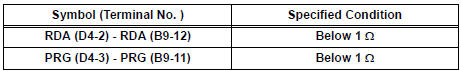
- Check the resistance between the wire harness side connectors.
Standard resistance
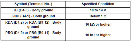
- Check the voltage and resistance between the D4 receiver connector or B9 ECU connector and the body ground.
Standard
2 CHECK DOOR CONTROL RECEIVER
- Check that the DTC is not output.
REPLACE MULTIPLEX NETWORK BODY ECU
 Diagnostic trouble code chart
HINT:
If a trouble code is displayed during the DTC check,
inspect the circuit listed for that code. For details of the
code, refer to the "See page" in the DTC chart.
...
 No Answer-Back (Hazard Warning Light and Wireless Door Lock
Buzzer)
No Answer-Back (Hazard Warning Light and Wireless Door Lock
Buzzer)
DESCRIPTION
If there is no answer-back of the hazard light signal and the wireless door lock
buzzer although the
wireless control function is operating normally, there might be a malfunction in
...
Other materials:
Installation
1. INSTALL PARKING BRAKE CONTROL PEDAL ASSEMBLY
(a) Install the parking brake control pedal assembly with
a bolt and the 2 nuts.
Torque: 39 N*m (398 kgf*cm, 29 ft.*lbf)
(b) Connect the parking brake switch connector.
(c) Connect the instrument panel junction block
assembly w/ wiring ha ...
Reassembly
1. INSTALL PLANETARY GEAR
(a) Apply grease to the planetary gears and pin parts of
the planetary shaft.
(b) Install the 3 planetary gears.
2. INSTALL STARTER ARMATURE ASSEMBLY
(a) Apply grease to the plate washer and the armature
shaft.
(b) Install the starter armature to the star ...
Reverse Signal Circuit
DESCRIPTION
The radio and navigation assembly receives a reverse signal from the
park/neutral position switch and
information about the GPS antenna, and then adjusts vehicle position.
WIRING DIAGRAM
INSPECTION PROCEDURE
1 INSPECT RADIO AND NAVIGATION ASSEMBLY
Disconnect the radio ...
