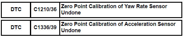
Toyota Sienna Service Manual: Zero Point Calibration of Yaw Rate Sensor Undone
DESCRIPTION
The skid control ECU receives signals from the yaw rate sensor via CAN communication system.
Yaw rate sensor has the built-in deceleration sensor.
If there is trouble in the bus lines between the yaw rate and deceleration sensor and CAN communication system, the DTC U0123/62 (yaw rate sensor communication trouble) and U0124/95 (deceleration sensor communication trouble) are output.
The DTC is also output when the calibration has not been completed.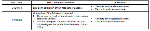
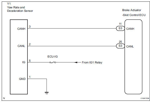
WIRING DIAGRAM
INSPECTION PROCEDURE
HINT: When U0073/94, U0100/65, U0123/62, U0124/95 or U0126/63 are output accompanied with C1210/36 or C1336/39, inspect and repair the trouble areas indicated by U0073/94, U0100/65, U0123/62, U0124/95 or U0126/63 first.
1 PERFORM ZERO POINT CALIBRATION OF YAW RATE AND DECELERATION SENSOR
(a) Perform the zero point calibration of the yaw rate and deceleration sensor (See page BC-70).

2 RECONFIRM DTC
(a) Clear the DTCs (See page BC-82).
(b) Turn the ignition switch to the ON position.
(c) Are the same DTCs recorded (See page BC-82).
Result

3 CHECK YAW RATE AND DECELERATION SENSOR INSTALLATION
(a) Check that the yaw rate and deceleration sensor has been installed properly (See page BC-197).
NOTICE: When replacing the yaw rate and deceleration sensor, perform zero point calibration (See page BC- 70).

REPLACE YAW RATE AND DECELERATION SENSOR
 ECM Communication Circuit Malfunction
DTC C1203/53 ECM Communication Circuit Malfunction
DESCRIPTION
The circuit is used to send TRAC and VSC control information from the skid
control ECU to the ECM, and
engine control information fr ...
 SM Solenoid Circuit
DTC C1225/25 SM Solenoid Circuit
DESCRIPTION
This solenoid turns on when receiving signals the ECU and controls the
pressure acting on the wheel
cylinders to control the braking force.
WIRIN ...
Other materials:
Television Display Power Source Circuit
DESCRIPTION
This is the power source circuit to operate the television display assembly.
WIRING DIAGRAM
INSPECTION PROCEDURE
1 INSPECT TELEVISION DISPLAY ASSEMBLY
Disconnect the connector from the television display
assembly.
Measure the resistance according to the value(s) ...
Eject Error/ Elevator Error/ Clamp Error
DTC 44-45 Eject Error
DTC 44-51 Elevator Error
DTC 44-52 Clamp Error
DESCRIPTION
DTC No.
DTC Detecting Condition
Trouble Area
44-45
Disc cannot be ejected.
Television display assembly
44-51
Mechanical error occurs during elevator operation.
...
Terminals of ECU
1. POSITION CONTROL ECU AND SWITCH ASSEMBLY
(POWER SEAT CONTROL SWITCH AND ECU)
Disconnect the P58 and P59 connectors.
Check the voltage of each terminal of the wire
harness side connectors.
If the result is not as specified, there may be a
malfunction in the wire harn ...
