Toyota Sienna 2010-2026 Owners Manual: Air conditioning controls
Adjusting the temperature setting
Turn the “TEMP” dial clockwise to increase the temperature and counterclockwise to decrease the temperature.
The “SYNC” button
The air conditioning system switches between individual (indicator( s) off) and simultaneous (indicators on) modes.
When the air conditioning system is in simultaneous mode, the passenger and/or rear side temperature will be synchronized with driver side’s.
- The air conditioning system switches simultaneous
Press the “SYNC” button. (indicators on)
- Driver side indicator
- Passenger side indicator When the indicator is on, the passenger side temperature will be synchronized with driver side.
- Rear side indicator When the indicator is on*, the rear side temperature will be synchronized with driver side.
*: When the rear air conditioning system is on.
- The air conditioning system switches individual
The temperature for the driver, passenger and/or rear seats side can be adjusted separately.
When all indicators on the “SYNC” button are on:
- Press the “SYNC” button. (All indicators will turn off.)
- The “PASS TEMP” dial is turned. (The passenger side indicator will turn off.)
- The “REAR TEMP” dial is turned. (The rear side indicator will turn off.)
When two indicators on the “SYNC” button are on:
- Press the “SYNC” button a second time. (All indicators will turn off.)
If both the temperature of the passenger and rear seats side are changed, all indicators on the button will be off.
Adjusting the fan speed setting
Press “ ” on
” on
 to increase the fan speed and “
 ”
”
to
decrease the fan speed.
Press to turn the fan off.
Change the airflow mode
To change the air outlets, press the “MODE” button.
The air outlets used are switched each time the button is pressed.
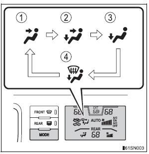
- Air flows to the upper body.
- Air flows to the upper body and feet.
- Air flows to the feet.
- Air flows to the feet and the windshield defogger operates.
 Front automatic air
conditioning system
Front automatic air
conditioning system
Air outlets and fan speed are automatically adjusted according
to the temperature setting. ...
 Using the automatic mode
Press the “AUTO” button (“AUTO” appears on the display).
Adjust the temperature setting.
To stop the operation, press .
Automatic mode indicator
If the fan speed setting or air flow ...
Other materials:
No. 1 Clearance Warning Buzzer Circuit
DESCRIPTION
The clearance warning ECU receives the ultrasonic sensor signal to sound the
front warning buzzer.
WIRING DIAGRAM
INSPECTION PROCEDURE
1 INSPECT FRONT BUZZER
Remove the clearance warning ECU with front buzzer.
Apply the battery voltage to the terminals 1 and 2 o ...
Mute Signal Circuit between Radio and Navigation Assembly and
Stereo Component Amplifier
DESCRIPTION
This circuit sends a signal to the stereo component amplifier to mute noise.
Because of that, the noise
produced by changing the sound source ceases.
If there is an open in the circuit, noise can be heard from the speakers when
changing the sound source.
If there is a short i ...
Engine hood courtesy
switch
Inspection
1. INSPECT ENGINE HOOD COURTESY SWITCH
Measure the resistance according to the value(s) in
the table below.
Standard resistance
If the result is not as specified, replace the hood lock
assembly. ...
